
Welcome to level 2 of the Stairway Series to Always On. This will be a fairly short article looking at SQL Server storage options. This will give you an idea of which types of storage are utilized for clustered and non-clustered systems. We'll look at the different types of storage that are available and what the requirements are for a standard Always On Availability group configuration.
Always On deployments utilize servers that are members of a single Windows Server Failover Cluster (WSFC) and each server typically has a standalone instance of SQL Server. In addition, each server will use its own local storage to store the standalone instances SQL Server database files (data files, transaction log files, backup files, etc). Although all the nodes are members of the same cluster, with no disk based witness or failover cluster instances, there isn't any shared storage provided. The shared storage single point of failure has been removed. However, Always On groups can use a failover cluster instance as an Always On availability replica. This not only re-introduces the shared storage single point of failure but also increases the complexity of the cluster as well increasing the required number of cluster nodes.
Getting back to basics, storage systems are essentially categorized as
- Localized
- Networked
Let's look at exactly what each of these terms mean.
Locally Attached Storage
Local storage is attached locally to the server; the disks are typically plugged directly into a hardware backplane, which in turn is connected directly to the server's main motherboard. Older configurations would possibly consist of a PCI bus expansion RAID controller that would be connected via 68 or 80 pin cables to the disks.
Below we see a typical view of modern, locally attached disk storage. The relatively short path and low complexity will provide for fast disk access. The backplane will have an Input\Output BIOS and will be used to control disk redundancy by creating RAID arrays across the local disks. However due to the limited space in the host computer case, a general maximum of 16 drives is the norm.
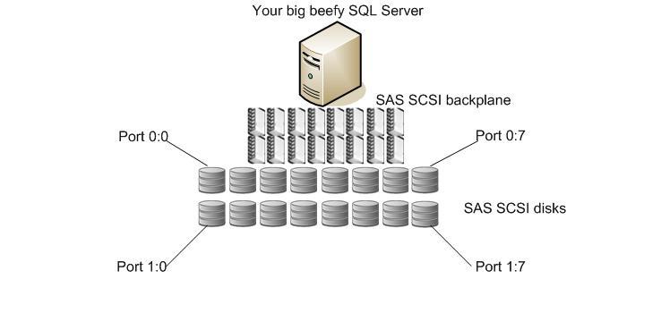
This would be typical of a standard storage configuration for a node with no network attached storage; no storage used for the individual replica is shared between other members of the Windows Server Failover Cluster. This also makes it easier to split nodes geographically as storage replication is not required.
Network Storage
Storage is networked to provide resources to a number of computer systems. Having a centralized storage repository can be easier to manage by reducing the management touch points across multiple separate arrays across each server.
Considering our scenario in the image below, there will usually be many hosts connected to the Fibre Channel (FC) network, this network is also referred to as the "Fabric". The computers are connected via a Host Bus Adapter (HBA) which is a little like a network card really.
Computers may also connect over iSCSI networks, these are relatively new and until recently, offered limited network speed (1 Gbps). They operate over a standard, segregated TCP\IP network. The computer will normally use a dedicated network card that is geared for iSCSI and employs a TCP offload engine. This simply means that the iSCSI traffic control is offloaded from the computer's CPU to the iSCSI cards onboard engine. Modern day iSCSI can handle traffic up to 10Gbps. One of the benefits to iSCSI configurations is that they are traditionally more affordable than a FC network fabric. However, they don't usually perform as well.
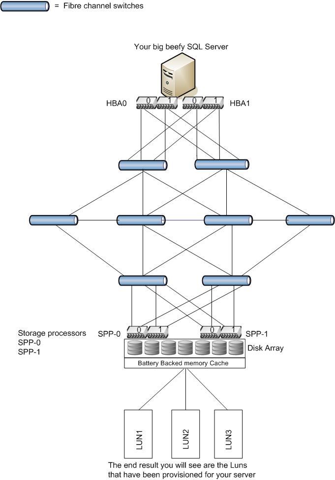
With many hosts all sending requests to and from the storage processor(s), you can quickly see how much traffic would be generated on the FC network. It's easy to see how, just like a TCP\IP network, the FC networks can get flooded. Performance issues on a storage area network are quite common in the network layer. On a complicated SAN setup, there will be multiple switches involving a large amount of cabling and additional power requirements. Looking at our base diagram above, we can see the complexity and the path the requests are required to take.
The path through the network just to get to the disk storage is complicated and consumes an element of time and when you consider that an I\O request is not considered complete until the request returns back from the SAN to the calling server.
This type of storage is the norm used for a failover cluster instance of SQL server, LUNs are "carved" out of the disk array, which will often be huge. The only drawback here is that the array will be formatted, typically using a 128K block size. This is not optimal for SQL server. The advantage here is that when configured correctly, storage requests hardly ever hit the back end array. Requests are written to a high speed memory cache, and the cache is then subsequently flushed to disk at an appropriate time so as not to impact performance. Upon a power failure, a battery backup will usually flush the cache to disk to avoid data loss. This is a high level description, but that is pretty much how it works.
There is another type of networked storage that may be used for sharing between a pair of High Availability nodes without the expense of having multiple host connections. This is referred to as Direct Attached Storage. These systems are specifically designed to use a private Fibre based connection, which can essentially be classed as localized. Below is a typical view of private High Availability storage configuration.
This scenario offers slightly better options over the localized storage if you wish to create private Highly Available clusters. Some storage vendors offer devices that connect over fibre channel cables and allow a maximum of 2 hosts to connect over multiple paths for high availability scenarios. This shared storage is connected to the hosts as shown below. Multiple array enclosures can be "piggy backed" to increase the amount of storage available.
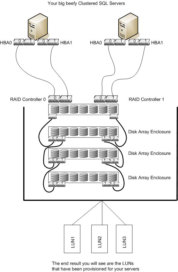
This type of storage is also used for Failover Cluster Instances (FCI) of SQL Server. It allows for the deployment of small clusters to service a particular environment maybe or simply just to provide shared storage to a limited number of hosts. You may well have this type of storage in use already.
You will have noticed the way the LUNs are potrayed in the diagrams above. The reason for this is because not all systems have the luxury of separate physical arrays to sit behind each Windows logical disk. In the scenarios above (and this is the most common configuration), the disks are set up as one large array.
Imagine a large cake, or in this case the array created form the pool of physical disks. A slice of cake is cut or in this case the LUN is then "carved" from the array and presented to Windows as the logical disk.
Conclusion
This concludes level 2 of the Stairway and will provide you with a firm grounding in the typical storage requirements for clustered and standalone SQL Server instances. In level 3 we will look a little closer at the remaining infrastructure requirements needed to support Windows Server Failover Clusters, Failover Cluster Instances and Always On Availability groups.