

Azure Data Factory is used for ELT (Extract, Load, Transform) operations in Azure. We do have multiple activities to move data from source and destination. However, we cannot do many data transformations using the general activities of Azure Data Factory.
Microsoft has introduced a Mapping Data Flow activity to do the transformation within the Azure Data Factory. In this article, we will understand what Mapping Data Flow activity is and how it works, and use cases of Data Flow activity.
What is the Mapping Data Flow activity?
Mapping Data Flows are visually designed data transformations in Azure Data Factory. As designed by Microsoft, Mapping Data Flows are zero code solutions for your ETL activity. If you have worked with SSIS or any other UI-based ETL tools then you can relate with Mapping Data Flows. The Mapping Data Flows can be scaled out also for high data processing requirements. ADF manages the clusters on which Mapping Data Flows run. Azure Data Factory handles the code transformation and execution of Mapping Data Flow behind the scenes. Azure Data Factory uses Spark cluster to execute Mapping Data Flow activity.
Now we will see how to use Mapping Data Flow and Implement a simple pipeline to understand the process in detail.
Add a Data Flow in an Azure Data Factory Pipeline
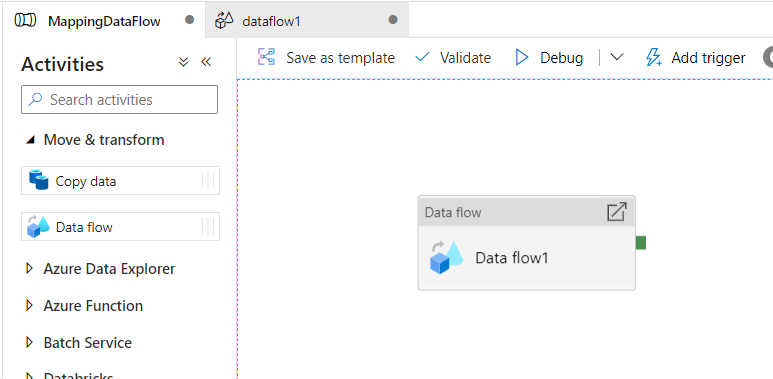
Open Azure Data Factory development studio and open a new pipeline. Go to the Move & Transform section in the Activities pane and drag a Data Flow activity in the pipeline design area. As specified in the below screenshot.
Once Data Flow is added to Pipeline you need to select Data Flow to see the settings or properties of a data flow. As shown below in the screenshot, there are multiple properties available in the settings tab of Data Flow.
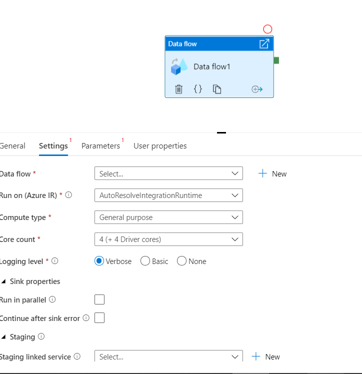
As you can see in settings, there is an option to select a Data Flow. If there is any existing Data Flow available and you want to run it in this pipeline, you can select it. As we don’t have any Data Flow activity, we will create a new one by clicking on the new button.
There are other properties also available that are required to run the Data Flow activity we are keeping them default as of now as shown in the above screenshot.
Designing a Mapping Data Flow
In the new Data Flow design window, you can see the Add Source option, as shown in the below screenshot.
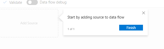
Figure 4: Data Flow initial window
Once you click on the Add Source, you will see the message in the below screenshot. It describes some basic details about the source.
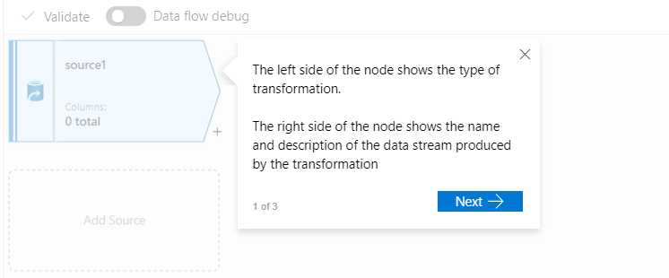
We need to add a data source using a dataset that we have already created to pull data from the SQL Server database. After providing the details to add a data source we will see the information as shown below screenshot.
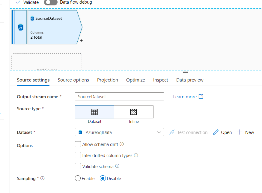
We have named this output stream as the source dataset in the above screenshot. Here we will provide the details of the dataset or table Data Flow _test.
Note: the assumption is that you are aware of the basic building blocks of a data factory-like creating linked services, datasets, Pipelines, etc.
There are multiple other properties that we will keep default as of now. Now, if you go to the projections tab as specified in the above image, you will see that the table schema has been imported as shown in the below screenshot.
In the table, two columns Id and Name are there, which are listed in the above screenshot. We will move this table to another destination table by implementing some transformation on one of the columns.
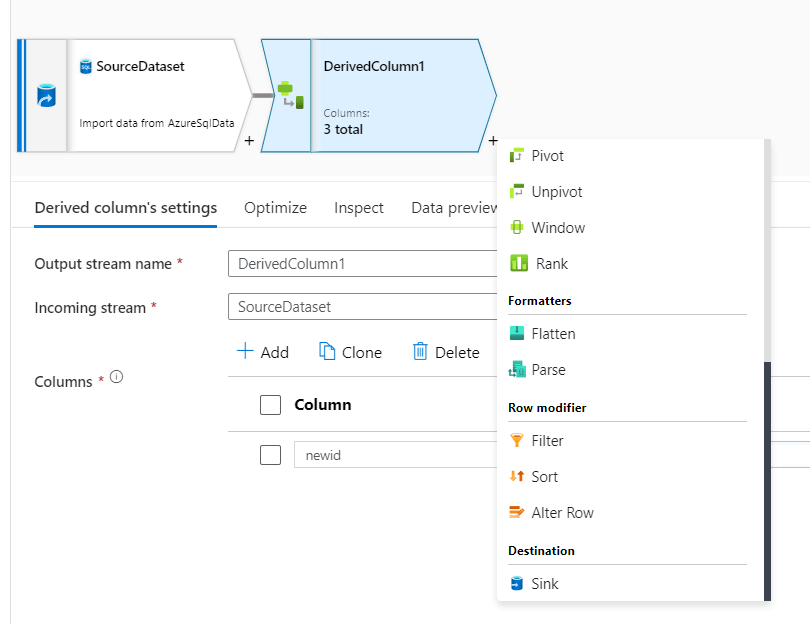
To add a transformation, we need to click on the + button on the data source as specified in the screenshot below.
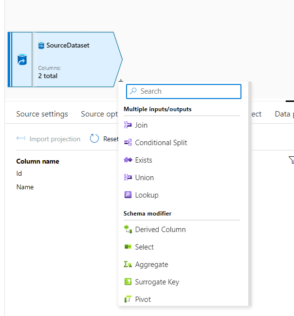
In the above screenshot, you can see there are various transformations available in the data flow. This is the only place in ADF where you can find out these easy-to-use transformations. To name a few, Join, Conditional Split, Exists, Union, Lookup, etc. We will read how to implement each of these transformations in more detail in our future articles.
For our current use case, we will use a derived column transformation. Click on derived column transformation from the list appeared at clicking + sing on the source.
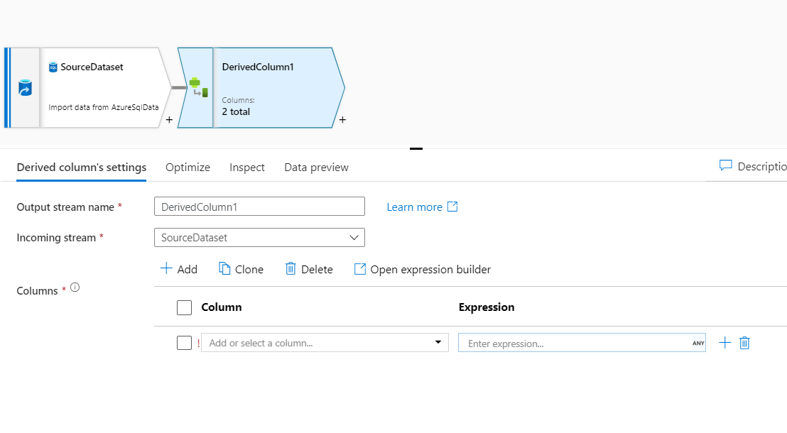
In the above screenshot, derived column transformation is added to the source. In this derived column transformation settings options, we notice that the incoming stream is the source dataset.
For configuring the transformation, we need to select the column from the input stream. Our use case will transform the Id column and create a new derived column new Id, which will sink into the destination table with other columns.
Name the column, Newid, and click on Any in the expression against the column. As you click on it there will be a new window as shown in the screenshot below. This window is the visual editor where we can transform an id column into a Newid column.
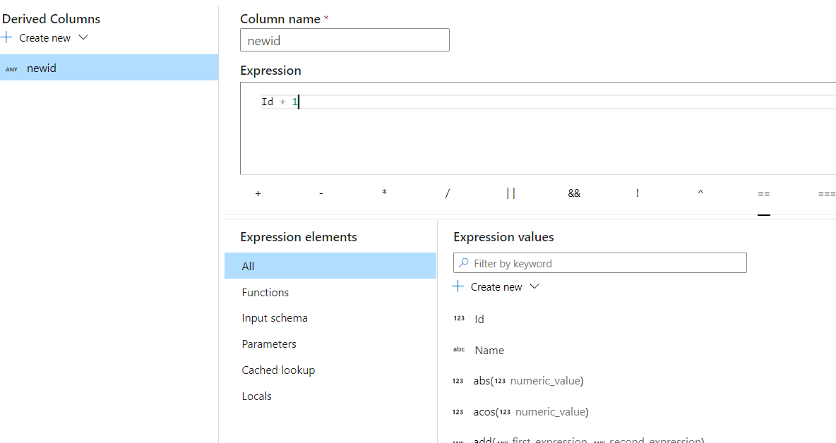
In this expression editor, we have added 1 to the ID column, i.e. it will add one to every id value, which will be stored on the Newid column for each row.
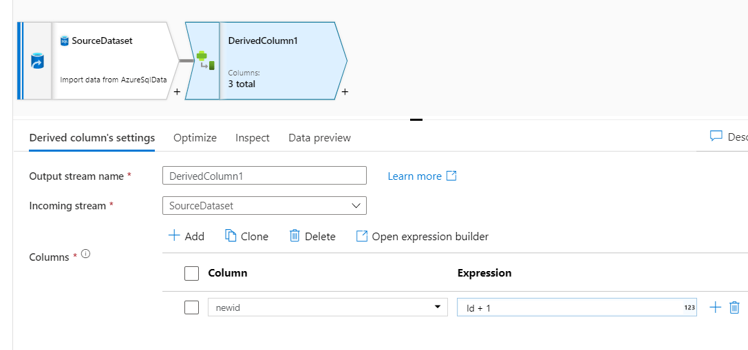
Many functions or expressions are available in this editor where we can perform complex transformation logic. After saving the expression window there will be a derived column as shown below.
You can see in the derived column it shows 3 columns as output, one newly created and the other two existing from the source.
We have created a new table which we will use to sink the transformed table. This transform table will have two columns.
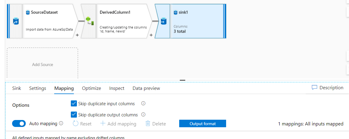
As shown in the above screenshot click on the + sign on the derived column and select sink destination from the list. Once you click on the sink will see the sink activity added to the pipeline as specified below.
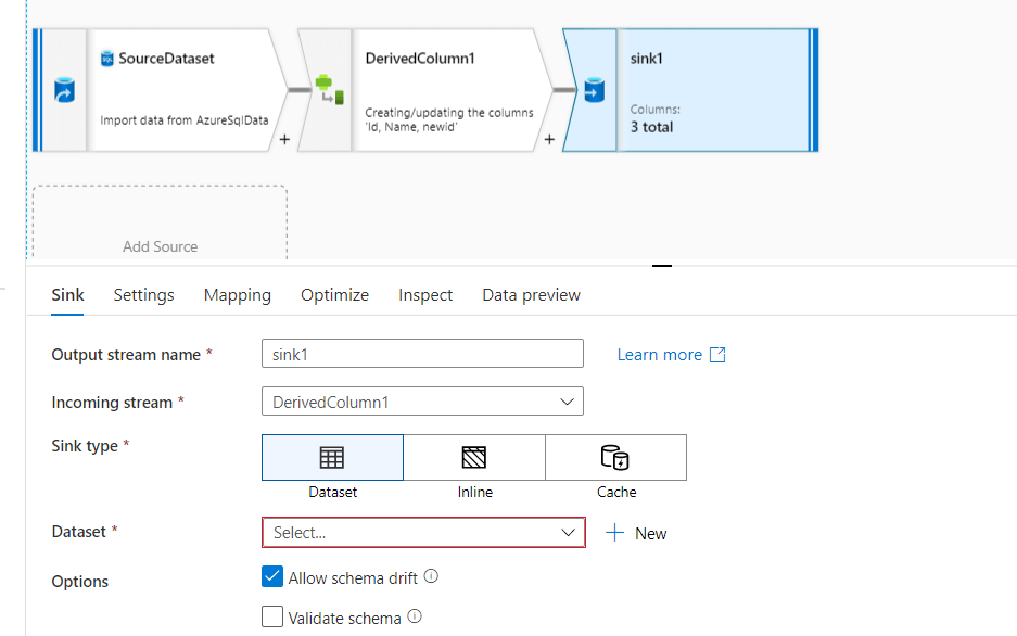
In the above screenshot, you can see the incoming stream coming from the derived column is connected to the sink destination. Now we will create the dataset for the destination to sink the data.

As you can see, the mapping option of sink automapping is enabled and all the columns from source derived column output stream are mapped to the sink.
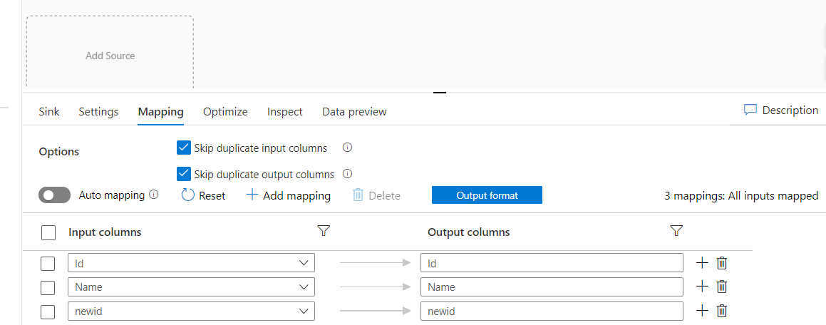
If you need to see the column mapping you need to disable auto-mapping as shown in the below screenshot.

As source and destination are mapped we will run debug in the data factory to execute data flow to transfer rows in destination tables or you can publish and trigger the pipeline also.
Once you click on debug in the data factory you will notice that the pipeline doesn't execute immediately which is because Data Flow prepares the cluster in the background before executing the Data Flow pipeline.
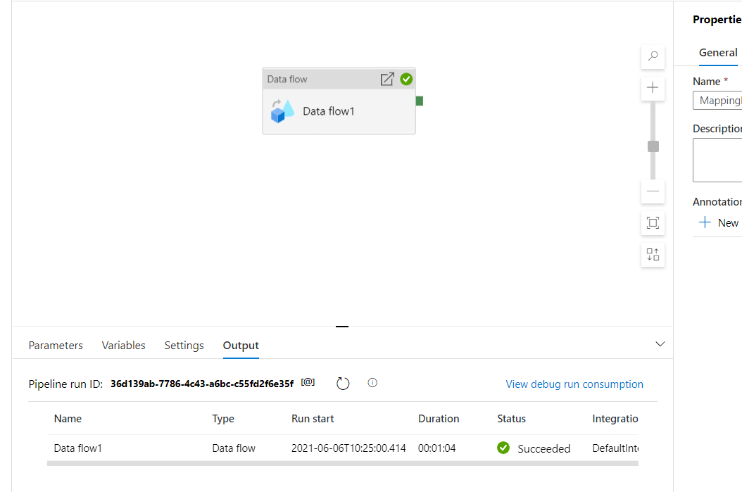
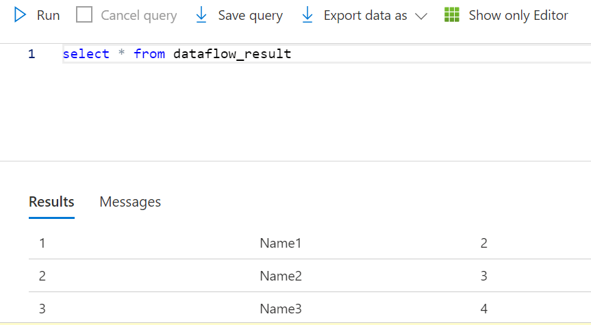
As you can see, the Azure data factory has executed the data flow and we see the rows are inserted into the destination table with new column values as shown in the below screenshot.
Conclusion
This is how we can leverage data flow for doing transformation on data without writing any code. This can help to reduce the complexity of code for developers and is easy to manage compared to writing code or SQL for transformation. You can implement Slowly Changing Dimension using Mapping Data Flow .