
This is the fifteenth article in a series entitled Stairway to Integration Services. Previous articles in the series include:
- What is SSIS? Level 1 of the Stairway to Integration Services
- The SSIS Data Pump - Level 2 of the Stairway to Integration Services
- Adding Rows in Incremental Loads – Level 3 of the Stairway to Integration Services
- Updating Rows in Incremental Loads – Level 4 of the Stairway to Integration Services
- Deleting Rows in Incremental Loads – Level 5 of the Stairway to Integration Services
- Basic SSIS Workflow Management – Level 6 of the Stairway to Integration Services
- Intermediate SSIS Workflow Management – Level 7 of the Stairway to Integration Services
- Advanced SSIS Workflow Management – Level 8 of the Stairway to Integration Services
- Control Flow Task Errors – Level 9 of the Stairway to Integration Services
- Advanced Event Behavior – Level 10 of the Stairway to Integration Services
- Logging – Level 11 of the Stairway to Integration Services
- Advanced Logging – Level 12 of the Stairway to Integration Services
- An Overview of SSIS Variables - Level 13 of the Stairway to Integration Services
- An Overview of Project Conversion - Level 14 of the Stairway to Integration Services
Introduction
In the previous installment we converted our original SSIS project to SSIS 2012 using SQL Server Data Tools – Business Intelligence (SSDT-BI). In this article, we will explore the first cousin of SSIS variables: SSIS parameters. We’ll demonstrate parameter configuration, dynamic property value management via package parameter, and how parameters are configured and used during SSIS package execution.
To begin, open the converted version of My_First_SSIS_Project in SQL Server 2012 Data Tools – BI as shown in Figure 1:

Figure 1
My_First_SSIS_Project opens and Solution Explorer appears as shown in Figure 2:
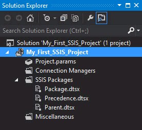
Figure 2
SSIS Parameters 101
SSIS parameters are a lot like SSIS variables. Variables and parameters are used interchangeably throughout SSIS 2012. There are a few important differences, though:
- Parameters are read-only once the SSIS package begins executing.
- Parameters are scoped at the Project and Package level.
- Parameters possess a Sensitive attribute.
- Parameters possess a Required attribute.
- Since Parameters are read-only once the SSIS package begins executing, Parameter values cannot be controlled using Expressions.
Project Parameters
Project parameters may be consumed by any SSIS package included in the SSIS project. They can only be used in the context of the Project Deployment Model.
The Project Deployment Model is new in SQL Server 2012 Integration Services. Project Parameters are one new feature of the Project Deployment Model. Other features include Package Parameters, Project Connection Managers, and deployment to the new SQL Server 2012 Integration Services Catalog.
In Solution Explorer, double-click the Project.params object in Solution Explorer to open Project Parameters, as shown in Figure 3:
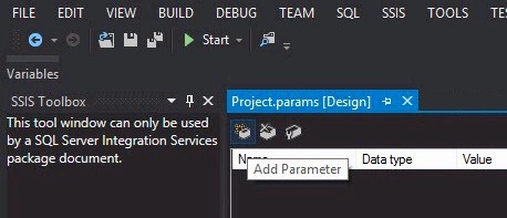
Figure 3
The Project Parameters window provides a toolbar containing three buttons:
- Add Parameter
- Delete Parameter
- Add Parameters to Configurations
Add Parameter
Click the Add Parameter button to add a new Project Parameter to the My_First_SSIS_Project SSIS project:
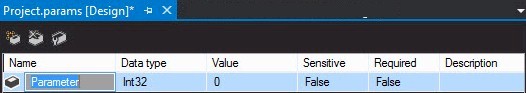
Figure 4
A new project parameter named “Parameter” is added to the SSIS project. This is the default parameter Name, and Figure 4 shows the parameter’s default property settings:
- Data Type: Int32
- Value: 0
- Sensitive: False
- Required: False
- Description: [Empty String]
Parameters and Variables share many data types, but not all – as Figure 5, with Parameter data types on the left and Variable data types on the right, demonstrates:

Figure 5
A scan of both lists reveals Parameter data types are a subset of Variable data types. Common to parameters and variables are the following data types:
- Boolean
- Byte
- DateTime
- Decimal
- Double
- Int16
- Int32
- Int64
- SByte
- Single
- String
- UInt32
- UInt64
Unique to Variable data types are:
- Char
- DBNull
- Object
The Value property of a parameter is checked for data type consistency once the Value cell loses focus. If I select the data type “Int32” and enter “NaN” into the Value cell, I get the error displayed in Figure 6 when I navigate to another cell in the Project.params grid:
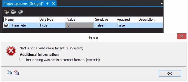
Figure 6
The Sensitive property is a Boolean (True or False) value that defaults to False. Setting this property to True marks the parameter value as sensitive. If True, SQL Server 2012 Integration Services will encrypt this value using the method specified in by the Project ProtectionLevel setting. You can access the Project ProtectionLevel property and other Project Properties by right-clicking the Project in Solution Explorer and then clicking Properties as shown in Figure 7:
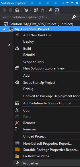
Figure 7
Clicking Properties causes the My_First_SSIS_Project Property Pages to display. Once the Property Pages display you can set the Project ProtectionLevel property by clicking the ellipsis in the ProtectionLevel property textbox. Clicking the ellipsis causes the Project Protection Level window to display, shown in Figure 8.
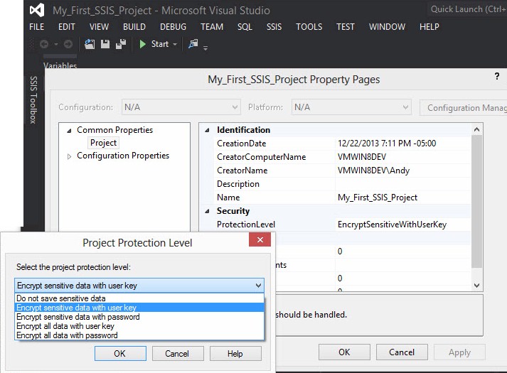
Figure 8
Please note in Figure 8: the Value property for the Parameter is masked once the Sensitive property is set to True.
The Required property is a Boolean (True or False) value that defaults to False. When set to False, the parameter is not required for SSIS Project execution. When set to True, a value for the parameter must be supplied for SSIS Project execution.
The Description property provides a means of documenting the purpose, usage, and optional values for the parameter.
For demonstration purposes, I have configured the parameter thus:
- Name: Parameter
- Data Type: Int32
- Value: 0
- Sensitive: True
- Required: True
- Description: Test Parameter
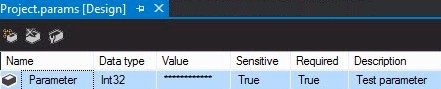
Figure 9
Delete Parameter
The Delete Parameter button will remove the selected parameter from the Project Parameters collection stored in the Project.params object. As Figure 10 shows, a warning is displayed, unless you override it by checking the “Do not show this message again” checkbox (I recommend that you do not check this checkbox), informing the data integration developer that packages that use the project parameter may fail to execute:
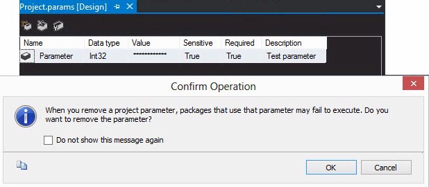
Figure 10
Package Parameters
Before we begin discussing SSIS package parameters, let’s add a new SSIS package to the project. In Solution Explorer, right-click the project name and then click “New SSIS Package” as shown in Figure 11:
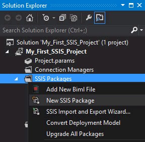
Figure 11
Rename the new SSIS package LoadWeatherData.dtsx as shown in Figure 12:
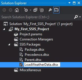
Figure 12
Renaming the SSIS package will cause the package to open in SSDT-BI. Package parameters are configured on the Parameters tab shown in Figure 13:
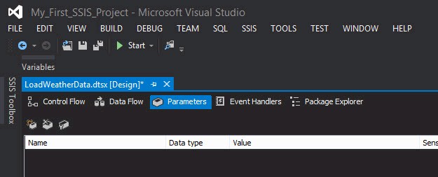
Figure 13
Before we configure an SSIS package parameter, let’s go get some real data. You can access a file containing real-world data by visiting this link (http://andyweather.com/data/WeatherData_Dec08.zip) as shown in Figure 14:
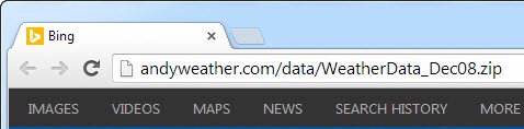
Figure 14
Unzip the file to the location of your choosing. It contains a comma-separated values (CSV) file named sensor1-all. I created a new folder named data in the SSIS solution directory for My_First_SSIS_Project, as shown in Figure 15:
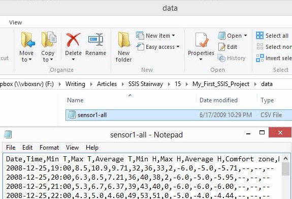
Figure 15
Sensor1-all.csv contains measurements collected from my personal weather station in Farmville Virginia. Whenever I train folks to develop data integration solutions using SSIS, I use this data. I like it because it’s real-world data, not sample data. It’s messy. No one’s data is as clean as most sample databases out there.
Package parameters are defined in much the same manner as project parameters. Let’s create a package parameter to contain the path where sensor1.all.csv is stored setting the following parameter properties, and shown in Figure 16:
- Name: SourceFilePath
- Data Type: String
- Value: <the location of sensor1-all.csv on your system>
- Sensitive: False
- Required: True
- Description: Weather data source file
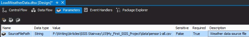
Figure 16
Let’s next return the Control Flow and add a Data Flow Task as shown in Figure 17:
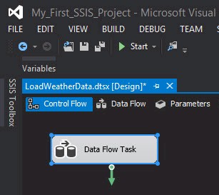
Figure 17
Rename the Data Flow Task “DFT Stage Temperature and Humidity” as shown in Figure 18:
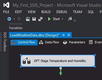
Figure 18
Double-click “DFT Stage Temperature and Humidity” to open the editor. From the SSIS Toolbox, expand the “Other Sources” category and drag a Flat File Source adapter onto the Data Flow Task canvas. Rename the Flat File Source “FFSrc Temperature and Humidity” as shown in Figure 19:
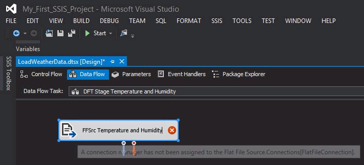
Figure 19
Double-click the “FFSrc Temperature and Humidity” flat file source adapter to open the editor as shown in Figure 20:
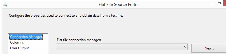
Figure 20
There are lots of ways to create connection managers. Here, I demonstrate the method I use almost every time. This method is simpler, easier, and requires fewer clicks.
There are no Flat File Connection Managers configured in this SSIS package. Click the New button to create and configure a new Flat File Connection Manager as shown in Figure 21:

Figure 21
Note that two things happened with that one click of the New button:
- A new Flat File Connection Manager was added to the Connection Managers tab (shown in relief in Figure 22); and
- The editor for this new Flat File Connection Manager was opened.
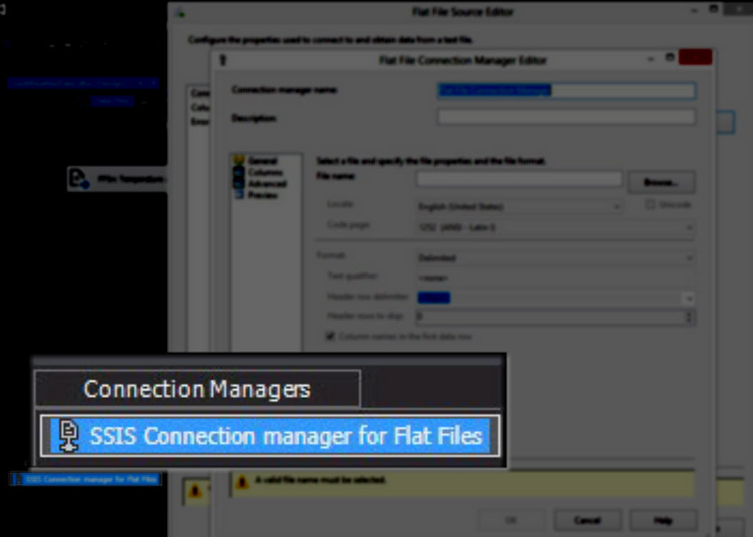
Figure 22
Rename the connection manager “FFCM Temperature and Humidity.” Click the Browse button, navigate to the folder where you stored the sensor1-all.csv file, and change the file type filter on the Open file dialog from “*.txt” (the default) to “*.csv”. the sensor1-all.csv file will then become visible for selection in the file list box as shown in Figure 23:
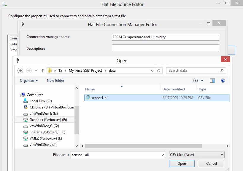
Figure 23
Select the sensor1-all.csv file and click the Open button.
The Flat File Connection Manager General page now shows the full path to the ensor1-all.csv file in the “File name” textbox. Make sure the “Column names in the first data row” check box is checked as shown in Figure 24:
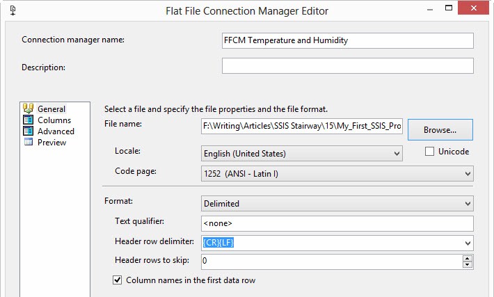
Figure 24
Don’t change anything on the Columns page. Note you can set Row and Column delimiters and you are provided a preview of the changes, as shown in Figure 25:
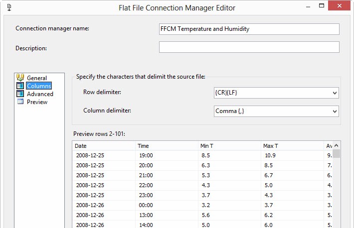
Figure 25
Figure 26 shows the Advanced page of the Flat File Connection Manager editor. We won’t make any changes on this page either, but we will make some observations. You can change the column Name and specify the Column Delimiter here for individual columns here. You can also alter the Data Type property. By default, all Flat File Connection Manager columns are set to the String Data Type with a Length of 50:
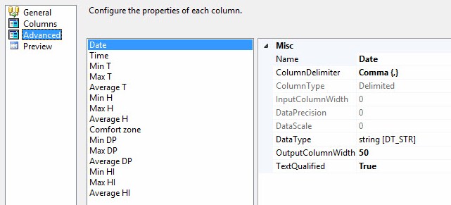
Figure 26
The Preview page of the Flat File Connection Manager allows you to configure the Connection Manager to skip some number of data rows. It also provides a grid previewing the first 100 rows of data, as shown in Figure 27:
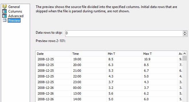
Figure 27
Click to Ok button to complete the FFCM Temperature and Humidity Flat File Connection Manager configuration and return to the Flat File Source adapter in the DFT Stage Temperature and Humidity Data Flow Task as shown in Figure 28:
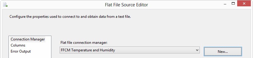
Figure 28
Click the OK button to close the Flat File Source adapter editor. The “DFT Stage Temperature and Humidity” Data Flow Task should now appear as shown in Figure 29:
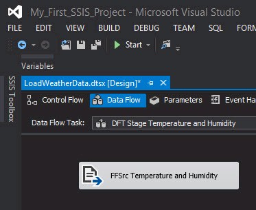
Figure 29
Before proceeding, open SQL Server Management Studio (SSMS) and connect to an instance of SQL Server. I’m using SQL Server 2012 and, as Figure 30 shows, I am connecting to my local default instance of SQL Server:
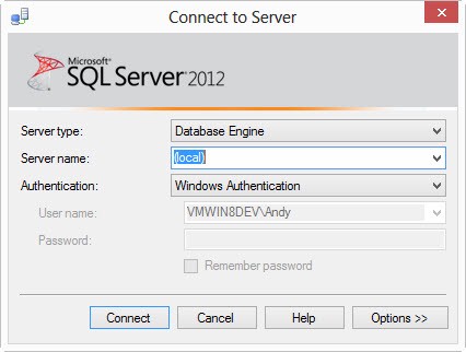
Figure 30
Open a new query window in SSMS and enter the text shown in Listing 1:
Use master
go
If Not Exists(Select name
              From sys.databases
                  Where name = 'WeatherData')
 begin
  print 'Creating database WeatherData'
  Create Database WeatherData
  print 'WeatherData database created'
 end
Else
 print 'WeatherData database already exists.'
Listing 1
The Transact-SQL (T-SQL) contained in Listing 1 checks to see if a database named WeatherData exists on your instance of SQL Server. If WeatherData exists, a message is returned informing you of this fact. If the WeatherData database does not exist in your instance of SQL Server, a message informs you the T-SQL engine is creating the database, then the database is created, and then a message returns informing you that the database has been created.
Why do I write T-SQL this way? That is an excellent question.
This is an example of an idempotent script. Idempotent means the operation can be repeated without changing the results. In Mathematics, adding 0 to a number will never change the value of the sum. It’s idempotent. The Transact-SQL script in Listing 1 can be executed and re-executed. The WeatherData database will exist at the completion of the execution, whether it’s the first or the tenth execution. It’s idempotent.
Jamie Thompson taught me the meaning of idempotent.
The first time I execute this script I get the results shown in Figure 31:

Figure 31
The second (and all subsequent) execution(s) generate the results shown in Figure 32:
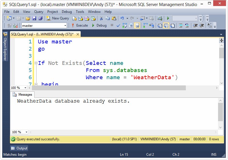
Figure 32
We can now put temperature and humidity data into the WeatherData database. Return to SSDT-BI. Drag an OLE DB Destination adapter onto the Data Flow surface as shown in Figure 33:
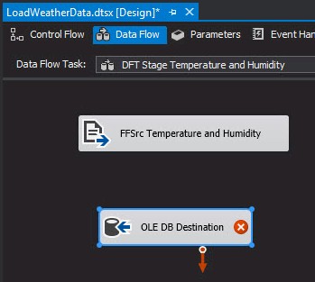
Figure 33
Connect a data flow path from the “FFSrc Temperature and Humidity” flat file source adapter to the OLE DB Destination adapter as shown in Figure 34:
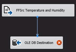
Figure 34
Rename the OLE DB Destination to “OLEDest Stage Temperature” as shown in Figure 35:
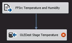
Figure 35
Double-click the “OLEDest Stage Temperature” OLE DB Destination adapter to open the editor as shown in Figure 36:
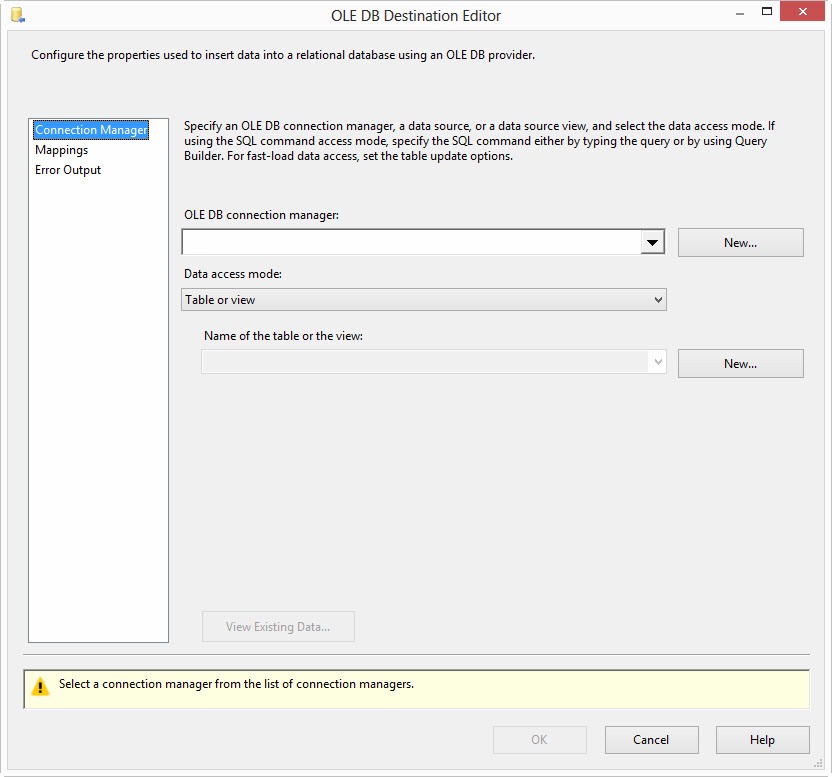
Figure 36
There are no OLE DB Connection Managers configured in this package – see Figure 37:
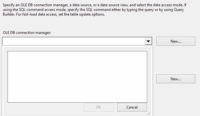
Figure 37
Click the New button beside the “OLE DB connection manager” dropdown to open the “Configure OLE DB Connection Manager” window as shown in Figure 38:
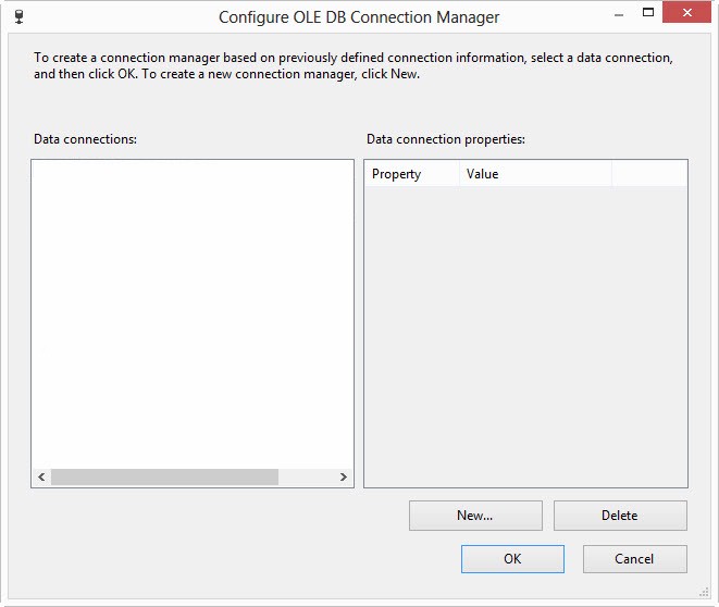
Figure 38
Click the New button to create a new connection manager configuration. In the “server name” dropdown, select or enter the name of the SQL Server instance that contains your WeatherData database. In the “Select or enter a database name” dropdown, select or enter WeatherData as shown in Figure 39:
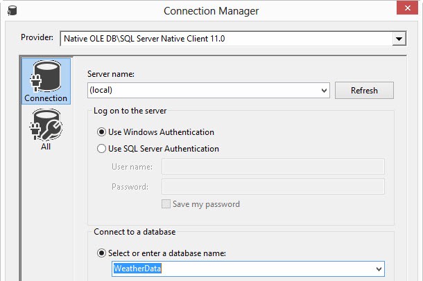
Figure 39
Click the OK button to close the Connection Manager editor. Click the OK button to close the “Configure OLE DB Connection Manager” window. The “OLEDest Stage Temperature” OLE DB Destination adapter should now appear as shown in Figure 40:
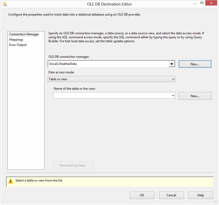
Figure 40
We will leave the “Data access mode” dropdown set to “Table or view”.
The “Name of the table or the view” dropdown is empty as shown in Figure 41:
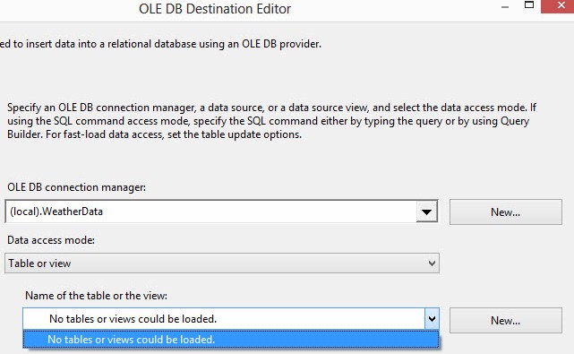
Figure 41
Click the New button beside the “Name of the table or the view” dropdown to open the Create Table window as shown in Figure 42.
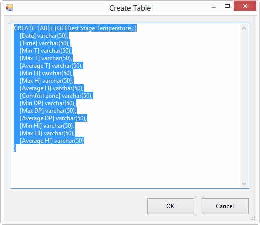
Figure 42
Edit the statement, removing the “OLEDest” and spaces from the table name, and the spaces from the column names as shown in Listing 2 below.
You can leave the spaces in the table and column names if you want, but – at some point – you will probably get tired if typing all those brackets and wish you hadn’t.
CREATE TABLE [StageTemperature] (
    [Date] varchar(50),
    [Time] varchar(50),
    [MinT] varchar(50),
    [MaxT] varchar(50),
    [AverageT] varchar(50),
    [MinH] varchar(50),
    [MaxH] varchar(50),
    [AverageH] varchar(50),
    [ComfortZone] varchar(50),
    [MinDP] varchar(50),
    [MaxDP] varchar(50),
    [AverageDP] varchar(50),
    [MinHI] varchar(50),
    [MaxHI] varchar(50),
    [AverageHI] varchar(50)
)
Listing 2
The CREATE TABLE statement was built from metadata sent into the OLE DB Destination adapter from the data flow path connecting the Flat File Source adapter to the OLE DB Destination adapter. When modified with the statement in Listing 2, the Create Table window will appear as shown in Figure 43:
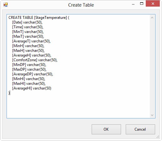
Figure 43
When you click the Ok button to close the Create Table window the Data Definition Language (DDL) CREATE TABLE statement is executed against the database, creating the StageTemperature table.
Click on the Mappings page in the OLE DB Destination Editor, as shown in Figure 44:
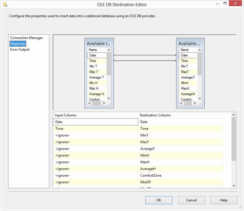
Figure 44
Note that auto-mapping occurs between the Date and Time input and destination columns. Why? Because these columns have the same respective names and data types.
I am uncertain of the rules for auto-mapping. If the column name and data type matches between the input and destination columns, auto-mapping occurs. If not, auto-mapping sometimes happens. Why? My best guess about the rules is: If the input column name matches the destination column name and the input data type can be coerced by SSIS into the destination data type, auto-mapping will occur. I base this hypothesis on eight years of observation. And I believe what is and what is not coercible has changed over the years. The only thing I’m sure of is: I don’t know.
The destination table was created from metadata collected from the OLE DB Destination adapter’s input. If you double-click on the data flow path connected from the “FFSrc Temperature and Humidity” flat file source adapter and the “OLEDest Stage Temperature” OLE DB destination adapter, you will find a metadata page, shown in Figure 45:
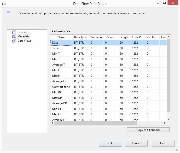
Figure 45
But remember, I altered the column names by removing the spaces. So the input column names contain spaces and most of the destination column names do not contain spaces.
There are a couple ways to map columns on the Mappings page. One way is to drag and drop column names from the Available Input Columns grid onto the Available Destination Columns grid (or from the Available Destination Columns grid onto the Available Input Columns grid – drag and drop mapping works both ways). Another way is shown in Figure 46. You can assign individual Input columns to Destination columns via dropdown:
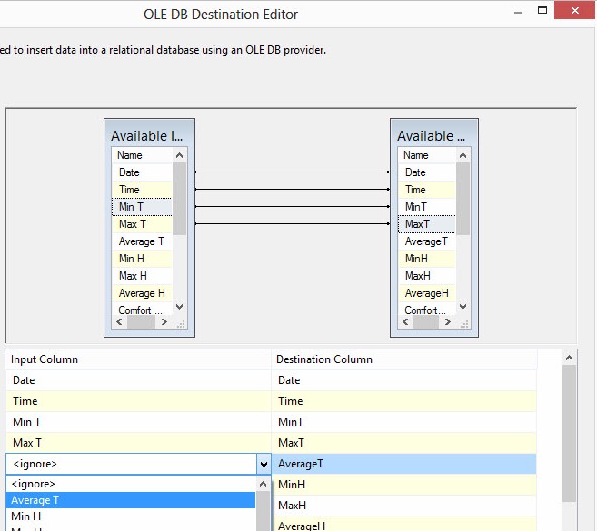
Figure 46
Once the mappings are complete, click the OK button to close the OLE DB Destination editor. Your data flow should appear as shown in Figure 47:
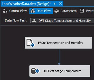
Figure 47
We are almost ready to execute. The last step is to map the SourceFilePath package parameter into the ConnectionString property of the “FFCM Temperature and Humidity” flat file connection manager. To accomplish this, click on the “FFCM Temperature and Humidity” flat file connection manager and press the F4 key to display the connection manager properties. Note the ConnectionString property is currently hard-coded to the path we selected earlier. To dynamically tie this property to the SourceFilePath package parameter, click the ellipsis in the Expressions property value textbox, as shown in Figure 48:
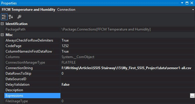
Figure 48
The Property Expressions Editor displays. Expressions allow developers to map expressions into property values dynamically at runtime. We can map the value of the SourceFilePath package parameter into the “FFCM Temperature and Humidity” flat file connection manager’s ConnectionString property by first selecting the ConnectionString property as shown in Figure 49:
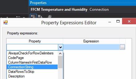
Figure 49
Click the ellipsis in the Expression textbox for the ConnectionString property to display the Expression Builder window shown in Figure 50:
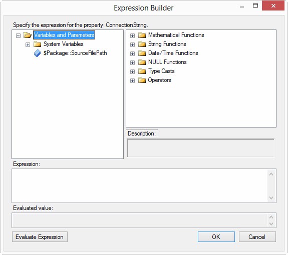
Figure 50
Expand the Variables and Parameters virtual folder and drag the package parameter $Package::SourceFilePath to the Expression textbox as shown in Figure 51:
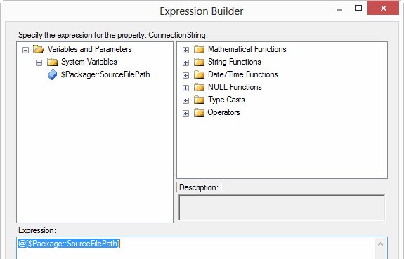
Figure 51
Click the Evaluate Expression button to see the value contained in the $Package::SourceFilePath parameter as shown in Figure 52:
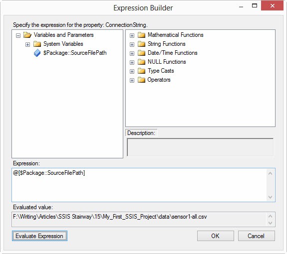
Figure 52
Click the Ok button to close the Expression Builder window. Click the OK button to close the Property Expressions Editor as shown in Figure 53:
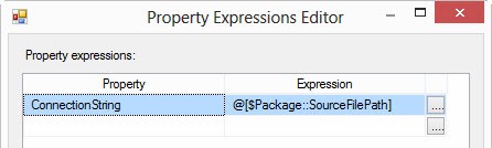
Figure 53
The “FFCM Temperature and Humidity” flat file connection manager’s ConnectionString property is now dynamically coupled to the value of the SourceFilePath package parameter ($Package::SourceFilePath) as shown in Figure 54:
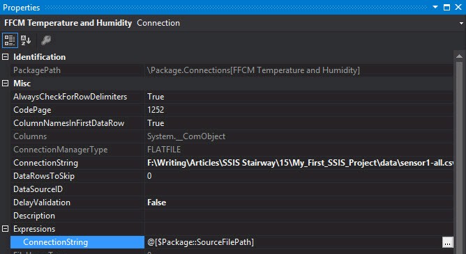
Figure 54
Press the F5 key to execute the package and test the loader as shown in Figure 55:

Figure 55
If all goes according to plan, your data flow should appear similar to Figure 55.
Stop the debugger and let’s move the source file. At the file’s current location, create a new folder named Dec08 and move the sensor1-all.csv file into the new Dec08 folder as shown in Figure 56:
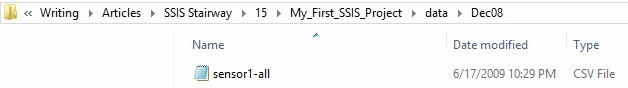
Figure 56
Return to the SSIS package and press the F5 key to re-execute the package. It should fail, displaying an error similar to the error shown in Figure 57:

Figure 57
Stop the debugger. Return to the Package Parameters tab and alter the value of the SourceFilePath parameter to include the Dec08 folder as shown in Figure 58:
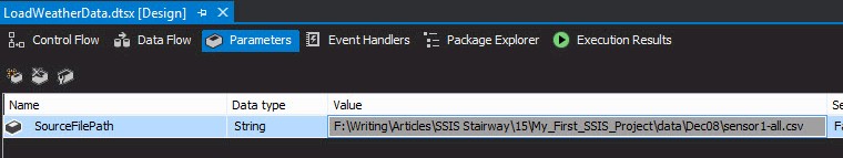
Figure 58
Now re-execute the package. Your results should appear as shown in Figure 59:
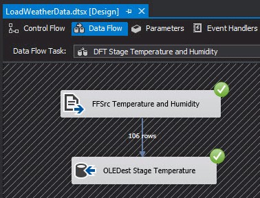
Figure 59
Test successful! We’ve made the path to the source file dynamic and used a package parameter to do so.
Conclusion
In this article, we explored SSIS parameters, parameter configuration, dynamic property value management via package parameter, and how parameters are configured and used during SSIS package execution.