

For a recent presentation on using availability groups for disaster recovery, I needed a test environment that contained multiple separate subnets – something that approximates what you’d see in an enterprise that has multiple remote data centers. I found bits and pieces of the configuration on other sites, but nothing comprehensive. This post will walk through the process of creating such an arrangement.
To create a simulated network, we’ll need some sort of virtual machine environment and an open-source software router. I use VMware Fusion (Mac) for my virtual machine, but you could use any VM environment that you have available. VirtualBox is another popular virtualization package; it’s free, and it’s available for Windows, Mac, and Linux.
There are a few open-source routers available online, but the one I chose to use is M0n0wall. It was readily available and small (only 9MB in size), and articles I found said that it worked well.
A working knowledge of network addressing (specifically private networks and subnets) is very beneficial for this project. If you need more information on private networks, refer to this TechNet article. For more information on subnets, refer to this Wikipedia article. You may also find this subnet mask cheat sheet helpful as you define your simulated networks – it translates the subnet masks we commonly see in Windows into the CIDR notation used by the router appliance.
Planning the Network
Before we begin, a bit of planning is in order. We’ll need a number of IP addresses for this project. Since this is a test environment, we’ll use addresses from the designated private address ranges: 192.168.0.0/16 (Class C), 172.16.0.0/12 (Class B), or 10.0.0.0/8 (Class A).
First, we need an IP address for the router itself, called the LAN address. This can be an address in the same subnet as your physical machine, but it doesn’t have to be. (If you do, note the subnet mask used by your machine’s network adapter. You’ll need it later.) In my example, I used 192.168.29.201 with a subnet mask of 255.255.255.0; this can also be written as 192.168.29.201/24.
Next, decide what address ranges you’d like to use for your simulated networks. You’ll need at least two subnets for this purpose. I like to use a completely different block of addresses for this to isolate the networks as much as possible from real traffic. You’ll need several addresses in each simulated network for your virtual machines, so make sure each subnet has plenty of room. In my example, I’ll use 10.1.1.0-10.1.1.255 (10.1.1.0/24) and 10.1.2.0-10.1.2.255 (10.1.2.0/24).
Finally, designate a subnet to use for a simulated WAN connection. We won’t go into the configuration of the WAN in this post, but I do plan to address it in a later post in this series. As before, I like to use a completely separate address block for this.
Conceptually, my network looks something like this:
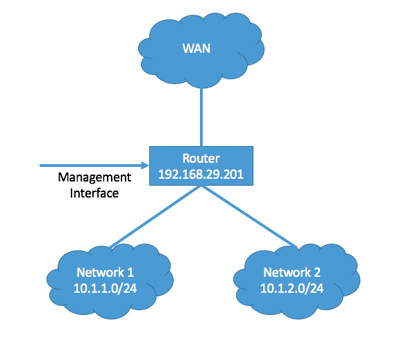
A word of caution: Make sure that none of the addresses you choose are used by any other devices on your network. Conflicts will cause those devices to become inaccessible.
Configuring the Router Virtual Machine
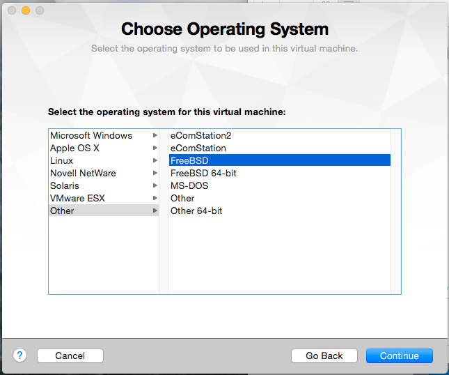
Now that you’ve defined the IP address scheme, we can create the virtual machine that will be used by the router. Create a new custom virtual machine in Fusion. When prompted, select Other FreeBSD from the list of OS options.
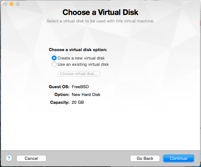
Select Create a new virtual disk. The default size of 20GB is fine for now; since Fusion only allocates space as it’s needed, you can reduce the size later if you want to.
When you reach the last screen of the wizard, click Customize Settings.
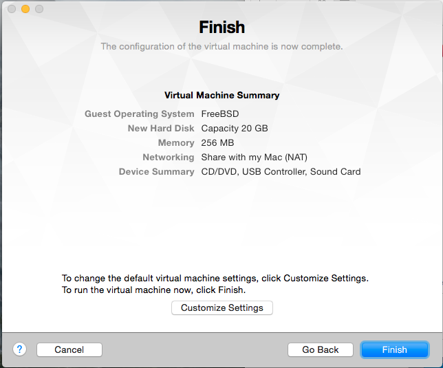
Give your virtual machine a name and click Save.
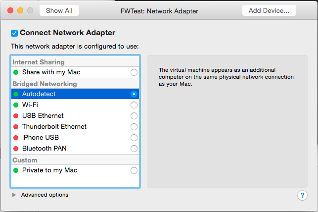
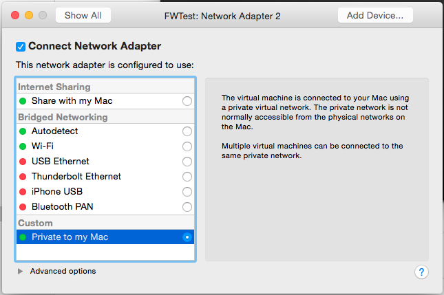
At the Settings screen, you’ll need to add a number of network adapters (NICs). You will need to have at least four in total:
- One for access from your LAN to allow you to manage the router (the management interface). This will be configured with Bridged Networking Autodetect.

- One for each subnet you want to simulate. These will be configured as Private to My Mac to prevent network traffic from outside your test environment from using them.
- One to simulate the WAN connection. This will also be configured as Private to My Mac.
Aside from the NICs, you can configure the VM to use minimal resources: 1 processor, 256MB RAM, no sharing, no 3D acceleration, small virtual disk. You can also remove unnecessary devices (such as USB/Bluetooth and Camera) if you want to further reduce its footprint.
Installing and Configuring the Router
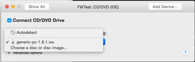
M0n0wall can be downloaded from http://m0n0.ch/wall/downloads.php. Select the CD-ROM image from the options at the bottom of the page.
Installation
Attach the .iso file you downloaded to the VM as a CD-ROM:
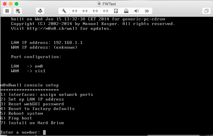
Now, start the VM. It should boot automatically from the image. Since M0n0wall is based on FreeBSD, it will generate a lot of text on boot. You will receive a warning as part of the boot process:
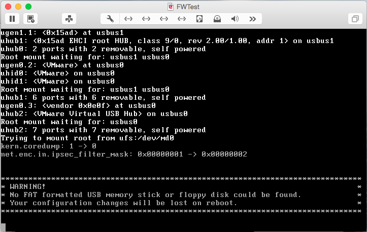
The warning is normal at this point, but we obviously want to save our configuration changes. Once the menu is displayed, select option 7 to install M0n0wall to the VM’s virtual disk:
You’ll be prompted with a list of available disks. After the prompt, Type the name from the first column (ad0) and press Enter.
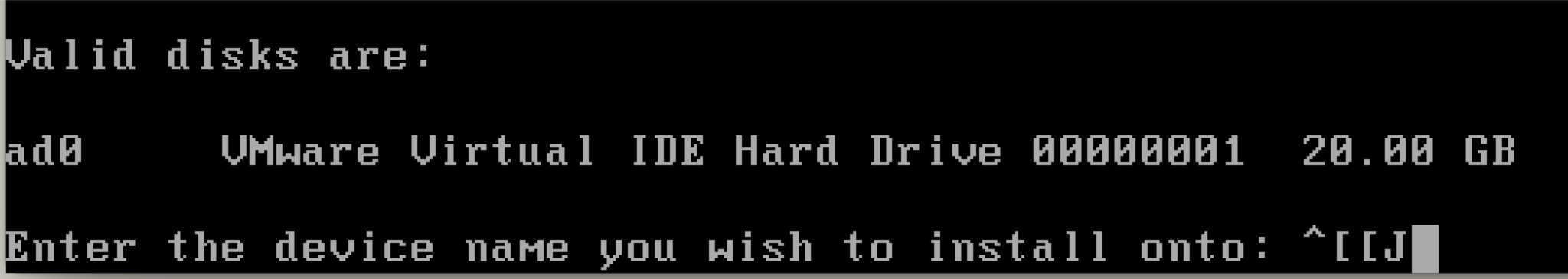
You’ll receive a warning that the process will erase the hard disk. Type y and press <Enter> to proceed and reboot.
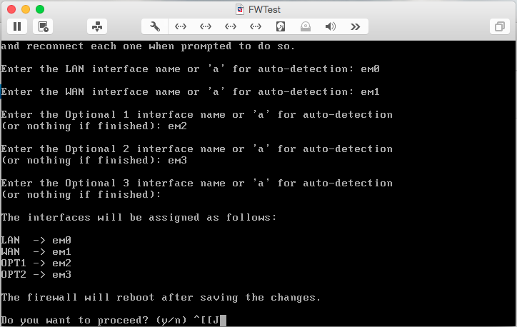
Port Configuration
Once M0n0wall reboots, you’ll notice a list of ports above the menu:
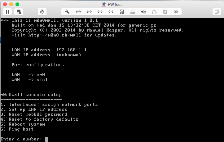
At this point, though, the list isn’t complete since we added 4 NICs to this VM. To change this, select option 1:
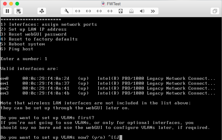
Type n and hit <Enter> to indicate that you do not want to setup VLANs. You’ll then be prompted to map the available interfaces. Configure them as follows, using the list of interface names provided by M0n0wall:
- LAN – em0
- WAN – em1
- Optional 1 – em2
- Optional 2 – em3
After the last interface has been added, press <Enter> to indicate you’re finished. Review your work, then enter y to reboot and save the configuration.
IP Configuration
After M0n0wall reboots, select option 2 to assign the IP address for the management interface:
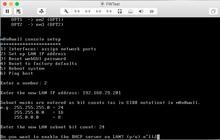
Enter the LAN address and subnet mask you chose. Enter n when asked if you want to enable the DHCP server.
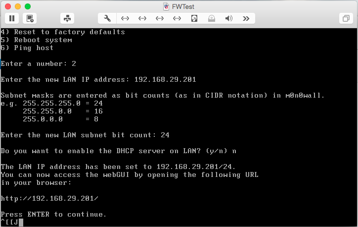
At this point, switch to the M0n0wall GUI to complete the configuration. In a web browser, enter the address of the management interface. In my case, the address is http://192.168.29.201/. When you’re prompted to login, use admin for the username and mono for the password.
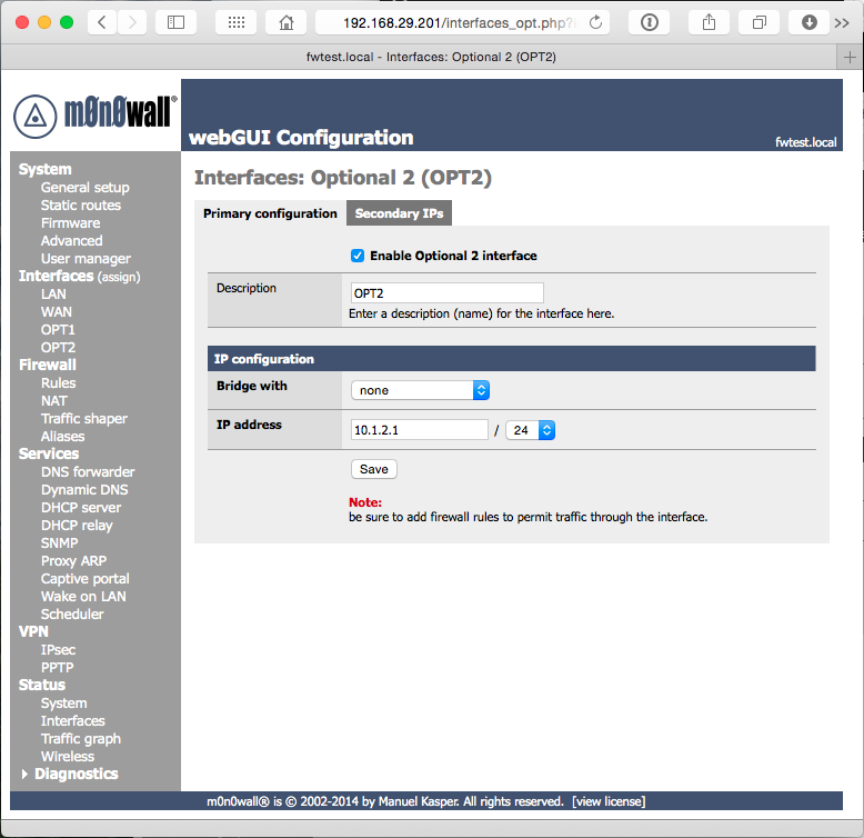
We’ll start by assigning the IP addresses for the “Optional” interfaces we defined earlier. Select Interfaces OPT1 from the left navigation, then check the box Enable Optional 1 interface. Enter an IP address from one of the network ranges you selected earlier, and select the appropriate subnet mask.

Click Save, and repeat the steps for your second network (OPT2).
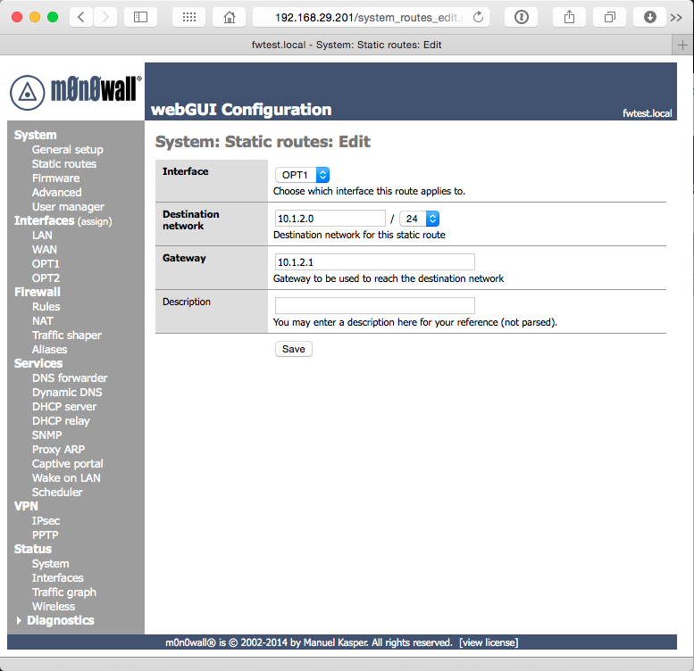
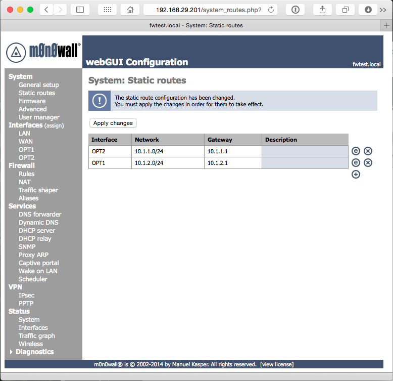
Now we need to tell the networks how to pass traffic to each other. In the navigation on the left, select System Static Routes. Enter one static route for each network interface (OPT1 and OPT2) by clicking the + icon. Select the network interface you’d like to configure in Interface. In Destination network, specify the starting address of the range for the other network (i.e., on the OPT1 interface, specify the starting address for OPT2’s network). Gateway is the IP address of the adapter of the other network (i.e., on OPT1, specify the address you assigned to OPT2). Click Save to complete this interface, and repeat. When you’ve finished with both routes, click Apply Changes.
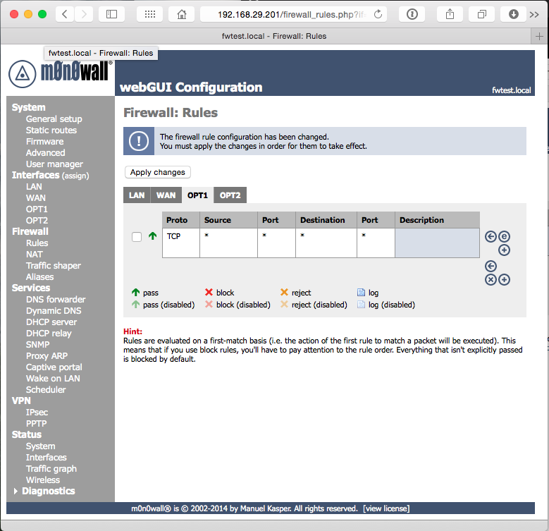
Finally, we need to configure M0n0wall’s firewall rules to allow traffic to pass between the networks. Because this is a test network, you can allow all traffic; in a real network, you would want to be much more specific.
Select Firewall Rules in the navigation, then click the OPT1 tab. Click + to add a rule. By default, the new rule will allow all traffic, so simply click Save at the bottom. Click Apply Changes, then repeat the steps for OPT2.
What’s Next?
Now that you have a router, you’re free to start setting up the other machines on your new virtual network. Stay tuned for follow-up articles on how to setup the domain and availability group.
[After I wrote this article, I found that the developer has decided to end development of M0n0wall. I plan to write a follow-up with a different firewall in the near future, but in the meantime, M0n0wall will still be a great option.]
This is my post for Week 3 of the SQL New Blogger Challenge. Check out all of this week’s posts on Twitter (#SQLNewBlogger).
![]()