
In the last level, we talked about how to construct the perfect SQL Server virtual machine on the VMware vSphere platform. In this article, we’ll create this same configuration on a Microsoft Hyper-V platform to maintain consistency. As with the other template, review and incorporate your own standards and policies into these recommendations as you build the virtual machine.
The following screenshots are taken from a Hyper-V 2012R2 using the Hyper-V Manager MMC plugin. SQL Server 2014 on a Windows Server 2012R2 operating system is used inside the guest. Other versions of SQL Server, Windows Server, and Hyper-V can be easily adapted from these instructions and screenshots.
Virtual Machine Specifications and Placement
Microsoft Hyper-V’s management is different from VMware vSphere’s in that you can use the Hyper-V Manager MMC plugin to manage the VMs themselves directly on a given host, or you can use System Center Virtual Machine Manager to centrally manage the environment.
For this article, we will be connecting into the individual host to configure and manage the VM.
You will need to install the Hyper-V management tools, which consists of the Hyper-V Manager and the Virtual Machine Connection, onto your workstation. These tools give you connectivity into the virtual machine console. Based on your operating system and Hyper-V version, install and configure the Hyper-V Tools using the following Microsoft TechNet article: Install and Configure Hyper-V Tools for Remote Administration.
Once installed, open the Hyper-V MMC plugin and connect to the host as shown in Figure 1. In my lab, the host currently has no VMs configured, but your environment might have existing VMs already present.
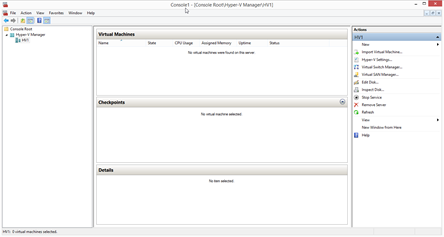
Figure 1
VM Configuration
Let’s start by building a new virtual machine for SQL Server. We’ll match the specifications and configuration details of the VMware-based VM from Level 3.
On the Actions column on the right, select New, and then select Virtual Machine. The New Virtual Machine Wizard will appear.
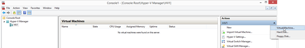
Figure 2
Select Next to begin the process, and then enter the new VM name.
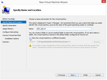
Figure 3
As shown above in Figure 3, the default location to store virtual machines could be a local disk, SAN-attached storage, or a SMB3 share on a network location. Check with your VM administrator to obtain the correct placement for this virtual machine. If the default location is not already specified, check the ‘Store the virtual machine in a different location’ box and specify the new storage location.
If you are on the most recent version of Hyper-V, 2012R2, you will see a prompt as shown in Figure 4, to select a virtual machine generation. The Generation defines the Hyper-V compatibility level, as well as defines certain options available to the VM, such as adding new virtual hardware components and online boot drive expansion in Generation 2 VMs. Whenever possible, select ‘Generation 2’, as it provides for newer features and compatibility levels that boost performance and configuration options. If there are multiple versions of the hosts and will potentially be moving the VM between them, select ‘Generation 1’.
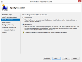
Figure 4
Virtual Memory
Figure 5 shows the next prompt for determining the amount of startup memory allocated to the virtual machine, and a checkbox for enabling ‘Dynamic Memory’ for this virtual machine.
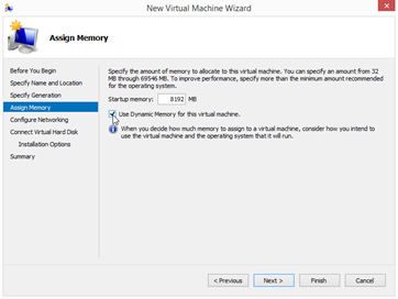
Figure 5
Host and VM-level memory management works differently between the VMware vSphere and Microsoft Hyper-V platforms. VMware treats memory as a fixed and finite amount per VM. However, the VMware hypervisor can oversubscribe memory based on the amount of memory the VMs actually consume. This feature represents how more memory than is physically present on a VMware host can be assigned to the VMs on the host. Oversubscribing the memory on a host can also trigger a memory reclamation process if the demand for memory exceeds the amount of memory the host contains.
Hyper-V’s powerful Dynamic Memory feature uses a different model of memory management. Dynamic Memory allows you to set a base amount of memory for the VM, and if the VM is under memory pressure, Hyper-V can dynamically add more memory. Windows operating system versions Windows Server 2008R2 SP1 and above support Dynamic Memory. Leveraging dynamic memory helps an administrator to size VMs, but monitoring each host to prevent host-level memory pressure states is still necessary.
More details can be found on Dynamic Memory at Microsoft TechNet.
It is worth noting that Tim Radney from SQLskills recently blogged about a limitation with Dynamic Memory allocations at SQLperformance.com. At the moment, the Dynamic Memory feature can only grow a VMs memory allocation by up to sixteen times the original memory allocation. Make sure to size your startup memory setting appropriately for the workload profile in order to not hit that limitation.
Based on the workload profile of your SQL Server, assign the appropriate amount of base system memory to this VM. I recommend enabling Dynamic Memory, but only if active monitoring of host-level memory pressure is configured. If you discover that Dynamic Memory is kicking in and adding more memory to a SQL Server VM, the SQL Server or other background processes could be putting memory pressure on the operating system. You should respond by either adding more startup RAM to the VM, or reduce the SQL Server maximum memory setting. If the reason for the increased RAM consumption is unknown, make sure to investigate to determine the root cause first. The consumption might warrant increasing the base system memory allocation, or reducing the SQL Server buffer pool max memory setting by a small amount. We’ll be configuring Dynamic Memory later on in the setup process.
Virtual Networking
The next step shown in Figure 6 involves assigning the correct virtual network to a new virtual network adapter. A new virtual network adapter is automatically added to the VM configuration as part of the wizard. The default connection will be the first virtual network available to you.
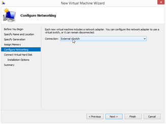
Figure 6
Your VM administrator should already have the primary server network to assign to this first network adapter. If not, the administrator should provide you the name of the appropriate virtual network. Don’t fret if you have additional networks to connect to this VM, such as cluster heartbeat, replication, or backup traffic, as you can add more networking adapters after the wizard finishes. Set the connection to the correct target virtual network.
Virtual Disks
The next step is to create a single hard disk to install the operating system onto. Additional SCSI controllers and virtual disks for the SQL Server installation and databases will be created later.
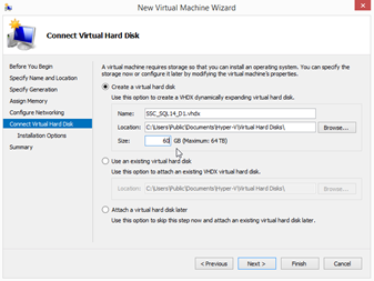
Figure 7
As shown in Figure 7, specify a name, location, and size for this virtual disk. Name the virtual disk appropriately with a consistent naming convention. A common naming convention is based on the machine name, disk number or purpose. Hyper-V Generation 2 VM virtual disks have a VHDX extension and can be as large as 64TB, whereas Generation 1 virtual disks have a VHD extension and have a maximum size of 2TB. Most operating system volumes are relatively small so in this example a 60GB drive will be configured. Make sure to place this disk in the same location as the virtual machine itself. As before, this location should be provided to you, and the C: drive of the Hyper-V host is not recommended for this location.
Additional Configuration
On the next step is the option to select an operating system installation media from an ISO file. I recommend selecting the bootable ISO image file now instead of later. By selecting an image now, the wizard will add the virtual optical drive for you automatically versus having to manually adding it later.
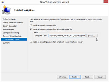
Figure 8
Your VM administrator should have the appropriate ISO containing the Windows version and edition required made accessible to the host. You will need the path to the ISO for this step. Specify the appropriate ISO and continue, as shown in Figure 9.
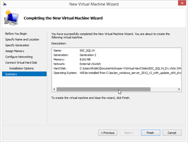
Figure 9
The final step presents a summary of your initial configuration options. Select ‘Finish’ to have Hyper-V construct this empty VM. At this point, we are not finished quite yet, but your VM should now appear in the list of virtual machines on this host.
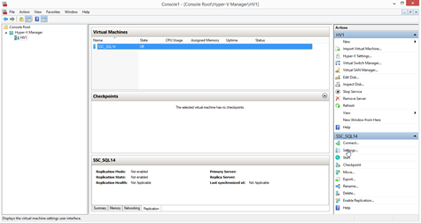
Figure 10
We now need to refine the virtual hardware configuration, and add additional virtual disks. After selecting your VM, select Settings on the Actions column on the right as shown in Figure 10.
Under the Firmware section, select the box to enable Secure Boot.
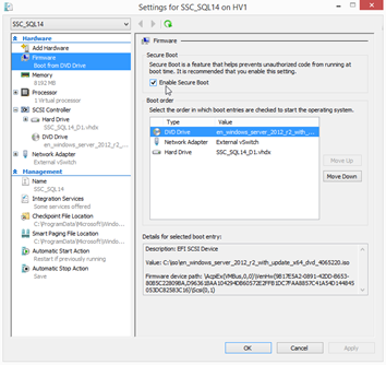
Figure 11
Secure Boot enables the UEFI firmware for the operating system, which helps improve the boot time of the VM, and enables drive-level encryption technologies.
Dynamic Memory
Under the Memory section shown in Figure 12, you can specify the memory ceiling that Dynamic Memory can expand the VM’s memory allocations up to.
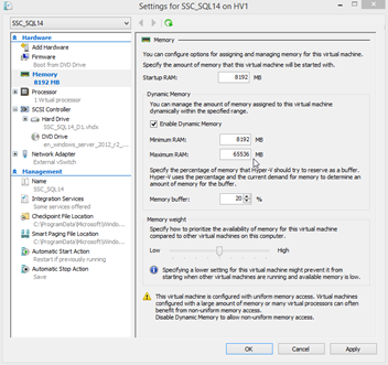
Figure 12
The maximum amount of RAM should be monitored as it relates to the overall memory allocations on the host to make sure that the host never reaches an overcommitted state.
The memory buffer percentage is the amount of memory above the base startup RAM value that Hyper-V will attempt to use as a file cache. SQL Server handles the management of the buffer pool independently of Windows or Hyper-V, so keep this value fairly small. The default is 20%. Microsoft’s SQLOS team recommends a 5% memory buffer percentage, but higher values can reduce low resource alerts within Windows. I usually keep these at the default values for smaller memory footprints and reduce it for VMs with large memory allocations. Once set, monitor the memory consumption and Dynamic Memory growth patterns to determine the appropriate setting after the VM is under normal operational load. The buffer will shrink back to the normal settings when the memory pressure subsides in recent versions of Hyper-V.
The final setting on the memory pane is the memory weight. Set this value based on the importance of the SQL Server workload, with a higher weight for the more important workloads. Try not to get too eager to tune unless you find performance problems, as additional layers of tweaking can lead to increasingly complex scenarios that complicate performance triage later on.
vCPU Configuration
Figure 13 below, shows the processor pane, which contains the virtual CPU configuration for the VM.
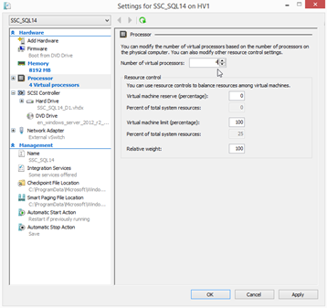
Figure 13
At first, the pane looks relatively straightforward, with just the number of vCPUs and resource options presented. Based on our right-sizing discussion from Level 2, you should already have a good idea of the number of vCPUs that this VM requires to function properly. Set the number of vCPUs here.
The resource control settings are a quick way to introduce performance trouble if these values are not set properly. Unless a given workload demands fine tuning to maintain top performance, these values are generally best left at the defaults.
The virtual machine reserve is the percentage of the amount of host CPU dedicated to this VM. A 10% value here would mean that two full physical CPU cores are dedicated on a 20-core host, which is possibly overkill and wasteful for most workloads.
The virtual machine limit is the maximum percentage of every physical CPU core that the VM can consume. If a VM consumes all of the physical CPU cores on an entire host, reserving a small amount of host CPU compute time might be necessary to maintain performance.
The relative weight allows an administrator to give priority to certain VMs to the physical CPU resources over other VM activities, but as always, adjust this setting only if your workload requires prioritization over others.
Advanced vCPU Configuration
If the Processor pane in Figure 14 is expanded, two options appear, Compatibility and NUMA.
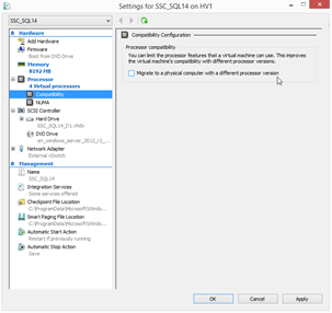
Figure 14
If you have a mixed processor physical cluster, enabling CPU compatibility can help you mix similar (i.e. same manufacturer, such as Intel or AMD), but not quite identical (such as Sandy Bridge or Ivy Bridge), hardware into one compute cluster. Mixing different CPU vendors changes the CPU instruction sets that are passed through into the virtual machines. If a Live Migration of a VM occurs from one host to another during this change, this can cause the operating system to become unstable. Therefore this configuration is not supported. However, hosts with similar CPUs can be added to the same virtualization cluster. The resulting instruction sets are passed into the VM in a compatible mode so that a common instruction set is maintained between the hosts thus allowing the VM to remain stable.
I usually enable this feature even if the cluster nodes are identical because if you introduce new hardware into the cluster a few years from now as part of a routine hardware upgrade, this feature allows for a seamless migration path. However, remember that any new hardware needs to support the same CPU vendor.
The NUMA pane is where the CPU configuration gets more interesting.
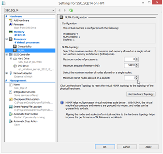
Figure 15
Figure 15 above, shows that you have flexibility to tune the VM to better match the host hardware configuration.
Note that at the top of the page, the configuration reflects the details as they are selected on the page.
The maximum number of processors setting under the NUMA topology section allows you to specify the maximum number of processors that a single VM can use simultaneously on a single virtual NUMA node. The same goes for the maximum memory as well. Ideally, you want your virtual machine to fit inside one of the physical NUMA nodes, and you would configure the VM here to better size it for one node. For example, if you have a two socket server with two 12-core CPUs and 128GB of memory, one NUMA node contains 12 cores and 64GB of RAM. If the VM resource footprint is smaller than or equal to these values, it can fit inside one NUMA node.
If the VM cannot fit inside one physical NUMA node, it should be configured to span across NUMA nodes. For example, if the VM requires 16 vCPUs and 96GB of vRAM, configure the number of processors at eight and the maximum amount of memory at 48GB. Those settings allow the VM to be split in half and span two physical NUMA nodes equally.
You can also attempt to put more than one virtual NUMA node on a single physical NUMA node with the last setting. However, this might result in performance penalties, so establish and monitor your performance baselines accordingly.
Virtual Disks
Next, we’ll move onto the virtual disks. First, we want to add three additional virtual SCSI controllers to the VM, and these will be added to the one that already exists. A maximum of four virtual SCSI controllers can be added to any given VM, and up to 64 virtual disks can be added to each virtual SCSI controller. These new components provide additional I/O queues inside Windows for improved performance. As with VMware, the virtual SCSI controllers are zero based.
Select ‘Add Hardware’, select ‘SCSI Controller’, and click Add.
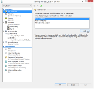
Figure 16
After adding the three SCSI controllers, we will add our new virtual disks. As with the VMware equivalent of this VM, eight virtual disks will be assigned to the VM.
This sample SQL Server virtual machine will be assigned eight virtual disks, representative of the workload to be placed on this example VM.
| Drive | SCSI ID | Size (GB) | Purpose |
| C: | (0:0) | 60 | Operating System |
| D: | (1:0) | 20 | SQL Server Instance Home |
| E: | (1:1) | 20 | SQL Server System Databases (master, model, msdb) |
| F: | (2:0) | 100 | User Database Data Files (1 of X) |
| L: | (3:0) | 40 | User Database Log Files (1 of Y) |
| T: | (1:2) | 50 | TempDB Data and Log Files (1 of Z) |
| Y: | (0:1) | 50 | Windows Page File |
| Z: | (1:3) | 100 | Local Database Backup Target |
Select the second SCSI controller on the left, shown below in Figure 17, then ‘Hard Drive’ from the list of new devices, then click Add.
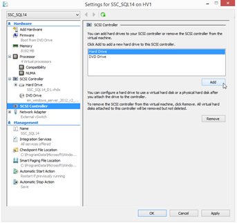
Figure 17
Once you have a new hard disk added to an individual SCSI controller, specify the SCSI ID by selecting the appropriate SCSI controller and then the location. For example, adding a new virtual disk for the SQL Server installation home from the above table would be accomplished by selecting the second SCSI controller and selecting location number one, resulting in a SCSI ID of 1:0.
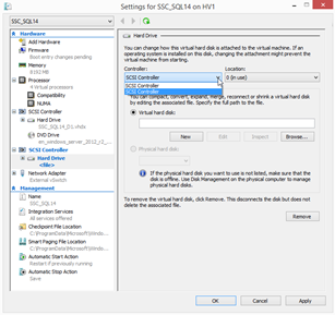
Figure 18
As shown in Figure 19 below, click ‘New’ underneath ‘Virtual hard disk’. This will add a new hard drive file to this virtual disk.
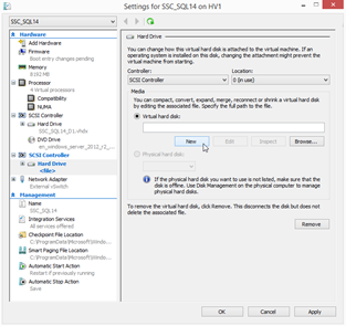
Figure 19
The first option that appears is to select the disk type.
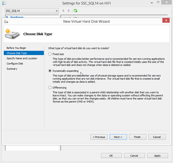
Figure 20
The fixed sized disk is a fully provisioned disk that is equal in size on the target file system to the allocated size, and is equal to a ‘thick provisioned’ disk within VMware environments. A dynamically expanding disk only consumes the amount of space on the SAN that is physical stored inside the disk, and is equal to a ‘thin provisioned’ disk within a VMware environment. Depending on your storage type and organizational policies, either one of these types might be appropriate for your usage.
A differencing disk is a format that allows an administrator to isolate changes on an underlying ‘base’ virtual disk so that changes can be easily rolled back. It is meant for short-term usage, and is not recommended for SQL Server VMs.
Next, name the virtual disk and specify the location for this new virtual disk file as shown below in Figure 21. Store the virtual disk in the appropriate location with the other virtual disks, unless you have a very demanding workload with a more advanced configuration. Dedicated storage locations or even additional storage devices can be used to help scale out the workload and improve performance or availability.
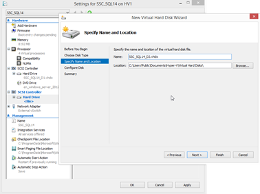
Figure 21
In Figure 22, specify the size of the virtual disk. You can also clone an attached physical disk or virtual disk, but this is rarely necessary for new SQL Server VMs.
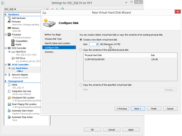
Figure 22
The last screen gives you the summary of your selections for this disk. Click Finish to add the disk to the VM. Perform this action for each of the virtual disks that you wish to add to this VM.
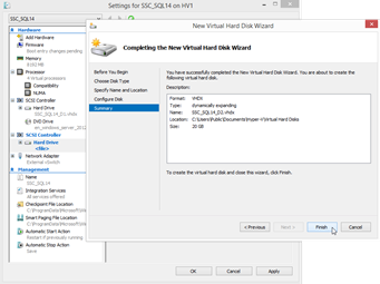
Figure 23
Finally, once you are finished adding the virtual disks, the last item to add is the integration components. Select Integration Services, and then check ‘Guest Services’ to allow integration with system-level utilities such as Volume Snapshot Service (VSS). Third-party applications, such as VM-level backup utilities, can leverage this feature for advanced actions that can help improve the efficiency of their products and reduce their impact on your SQL Servers at the same time. The other options on this tab are checked by default, and it is recommended to leave them checked unless your specific server requires a nonstandard configuration.
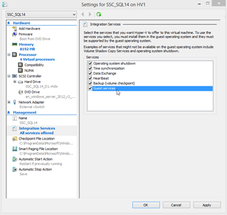
Figure 24
Operating System
At this point, you should be ready to install the operating system. Select your new virtual machine. On the right column, select ‘Start’.
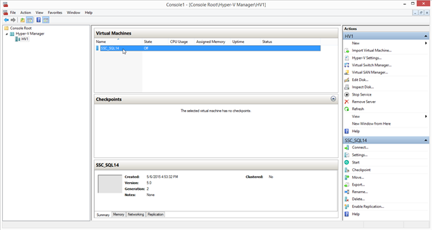
Figure 25
Once started, click ‘Connect’. The console for the hypervisor now appears, and the installation prompts for the virtual machine OS should now be displayed. This activity is from the bootable operating system ISO image specified during the VM creation wizard.
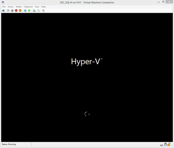
Figure 26
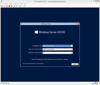
Figure 27
At this point, install the Windows Server operating system. As shown below, make sure to select the first virtual hard disk to install the operating system onto.
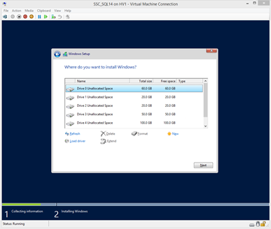
Figure 28
Once completed, the Hyper-V Integrations Services should be installed. If you used the wizard to select and install the OS, these might be installed as part of the OS installation. You can check if these are installed by reviewing the list of installed packages in the Programs and Features option in the Control Panel.
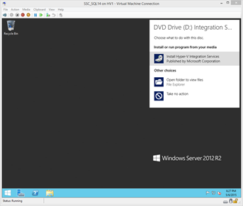
Figure 29
Reboot and fully patch the operating system just as you would do with a physical server.
Once patching is complete, enter the Computer Manager, select Disk Management, and bring the secondary disks online.
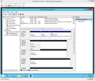
Figure 30
As shown in Figure 31 below, initialize the disks as the GPT format so they could grow beyond the 2TB limit of MBR-initialized disks if needed.
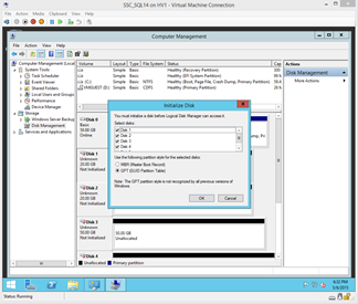
Figure 31
Label each disk according to its purpose for ease of management. Format each disk to the 64KB NTFS allocation unit sizes, per Microsoft’s best practice recommendations for SQL Server.
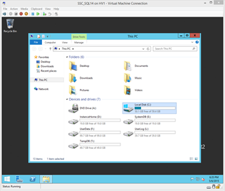
Figure 32
Your Hyper-V-based virtual should now resemble the screen shown in Figure 32 in the Hyper-V Virtual Machine Connection console. You are now ready for the next step of installing and configuring a new SQL Server instance per your normal operational practices.
Summary
This Level outlines the Hyper-V-based build process for an ideally configured SQL Server virtual machine. The logical build process for Hyper-V is similar to VMware-based platforms, with different nuances around items such as memory management, but the end result is the same – you now have a VM that is ready for you to install SQL Server onto and begin your data migration. Stay tuned for the next level, as it describes the performance validation of this new environment when compared to its physical equivalent!