Most of the time, we can create tables perfectly adequately using our preferred GUI tool. However, for complex tables, a GUI can’t always provide what we want, or even if it does, it is often quicker and easier to use code.
The “Backus-Naur Form (BNF)” diagrams on MSDN, the format of which I’ll review briefly towards the end of the article, explain every syntax detail, but in a form that is very hard to digest and keep in the head, well in my head anyway. Often, I find myself reverse engineering the syntax from the examples.
The aim of this article is to provide a smooth route through the syntax, by means of railroad-style diagrams. I developed these diagrams, initially, while creating a SQL-based build-script generator and trying to learn some of the more esoteric aspects of the SQL Server 2012 CREATE TABLE syntax. However, I soon became convinced that others might find them useful. I found that the details “stuck” far more quickly when learning from a diagram and through their use, I uncovered several interesting facts about how SQL Server 2012 CREATE TABLE works that had eluded me previously.
Diagrams, not words
To create a table in SQL Server, we just need to use the CREATE TABLE command, give the table’s name and a list of the columns we need. We can also specify where the table is to be stored and provide some table options, including constraints.
To describe this in more detail would take too many words, so I’m going to use diagrams instead. These are railroad, or syntax, diagrams and you encounter them occasionally in SQL. SQLite, for example has them for its documentation, and so has Oracle.
With a syntax diagram, there is only one entry point and one exit point. We start at the entry point and read from left to right. We can take any of the possible paths or railway lines to the exit, but we can only travel in one direction along each path.
I’ve changed tradition slightly by running down the page as well as from left to right, but elsewhere, I’ve adhered to the following conventions:
- Commands and other keywords appear in UPPERCASE inside rectangles, and we type them literally, exactly as shown in the rectangles.
- Parameters appear in lowercase inside ovals. We generally substitute our own information, such as names of tables, columns, numbers or expressions for the parameters . If parameters are within angle-brackets they represent an entire diagram.
- Punctuation, operators, delimiters, and terminators appear inside circles.
Where the syntax gets a bit dense, I’ve taken the liberty of putting the punctuation with the associated symbol rather than separating out the punctuation in its own circle. I’ve only done this where space is a bit tight and the usage is unambiguous.
Using a Syntax Diagram
Once you get the hang of a railroad diagram, they are a glorious way of getting to understand syntax quickly. Start at the top, the terminus, and travel along the railway system. You can only go one way. As with any railway map, there are certain sections, akin ot the suburban lines around and through major cities, which require an “exploded view” to show the details.
At such points, the parameter in the oval appears in angle brackets ( <>). This signals that, for detail, we need to change temporarily to a more detailed map. When a syntax diagram aims to be so complete that someone can use it to engineer a parser, it can get quite intricate. Fortunately, this isn’t the case with our diagrams.
The SQL Server 2012 CREATE TABLE Syntax Diagrams
Evey diagram that follows is done in reduced definition so it fits on the page. Click it to see it a decent size, or use the PDF file to view it or print it out in a good working size. The PDF files are in the downloads at the bottom of the article.
Although there is only one high-level diagram to consider for creating a table, we may require five other detail diagrams at certain parts of our journey. I provide each diagram as a separate PDF file, as part of the code download with this article (see the speech bubble to the right of the article title). They are readable when printed out in A4 but I like to print them as A3 wall-charts.
The annotations that you’ll see on each diagram are quotes taken from MSDN, to whom all credit must go. The words in the MSDN CREATE TABLE page are all smithed with great care. Whereas I’ve spotted errors in the syntax BNF on the page, the words have always been spot on, and packed with information.
Let’s take a short example of use, taken from the create_table_overview diagram.
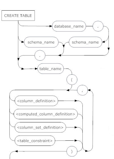
The entry point is CREATE TABLE. From here, we can qualify the table name with the database name and schema name, each separated by a full stop ( MyDB.MySchema.MyTable) or we can just qualify with the schema, or we can simply enter the table name.
After an opening bracket, we hit the <column_definition> junction, where if required we can jump to the Column Definition syntax diagram for details of how to define the required columns.
A comma separates one column definition from another, or from a computed column definition, or a column constraint definition, and so on. In this fashion, we work our way through the railroad network, in the directions of the arrows, and making a choice at every junction.
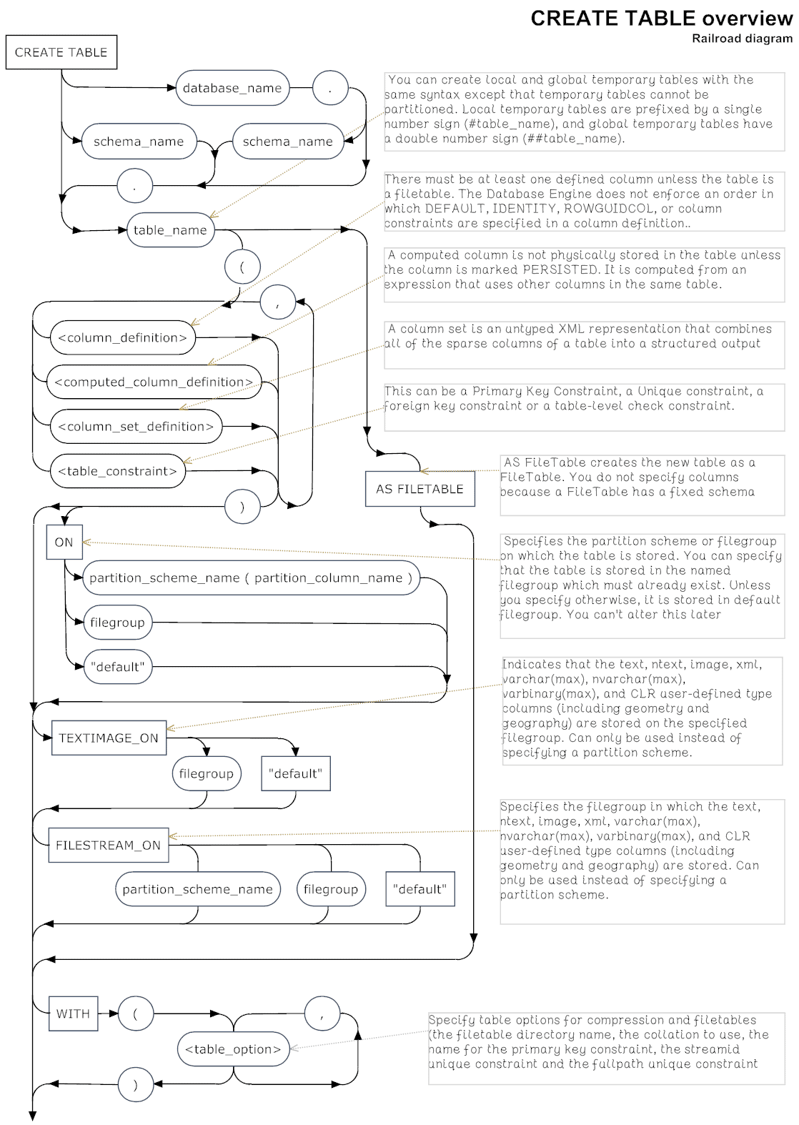
CREATE TABLE overview syntax
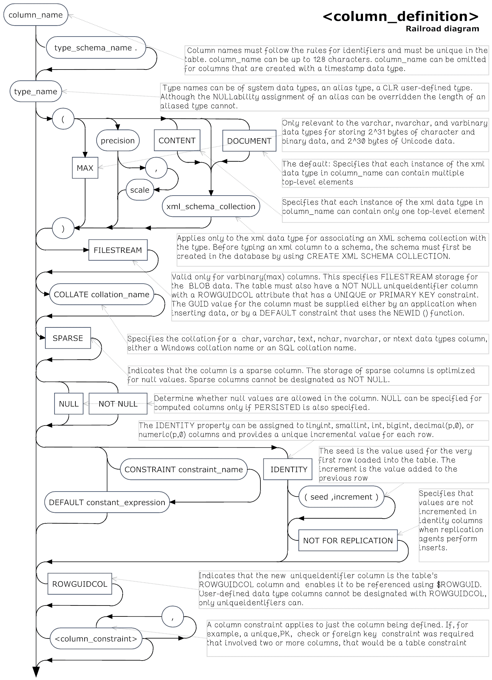
The Column Definition syntax
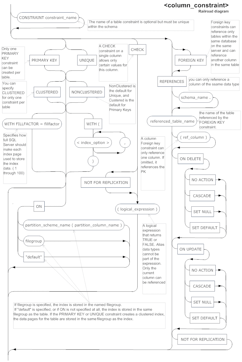
Column Constraint syntax
Computed Column Definition
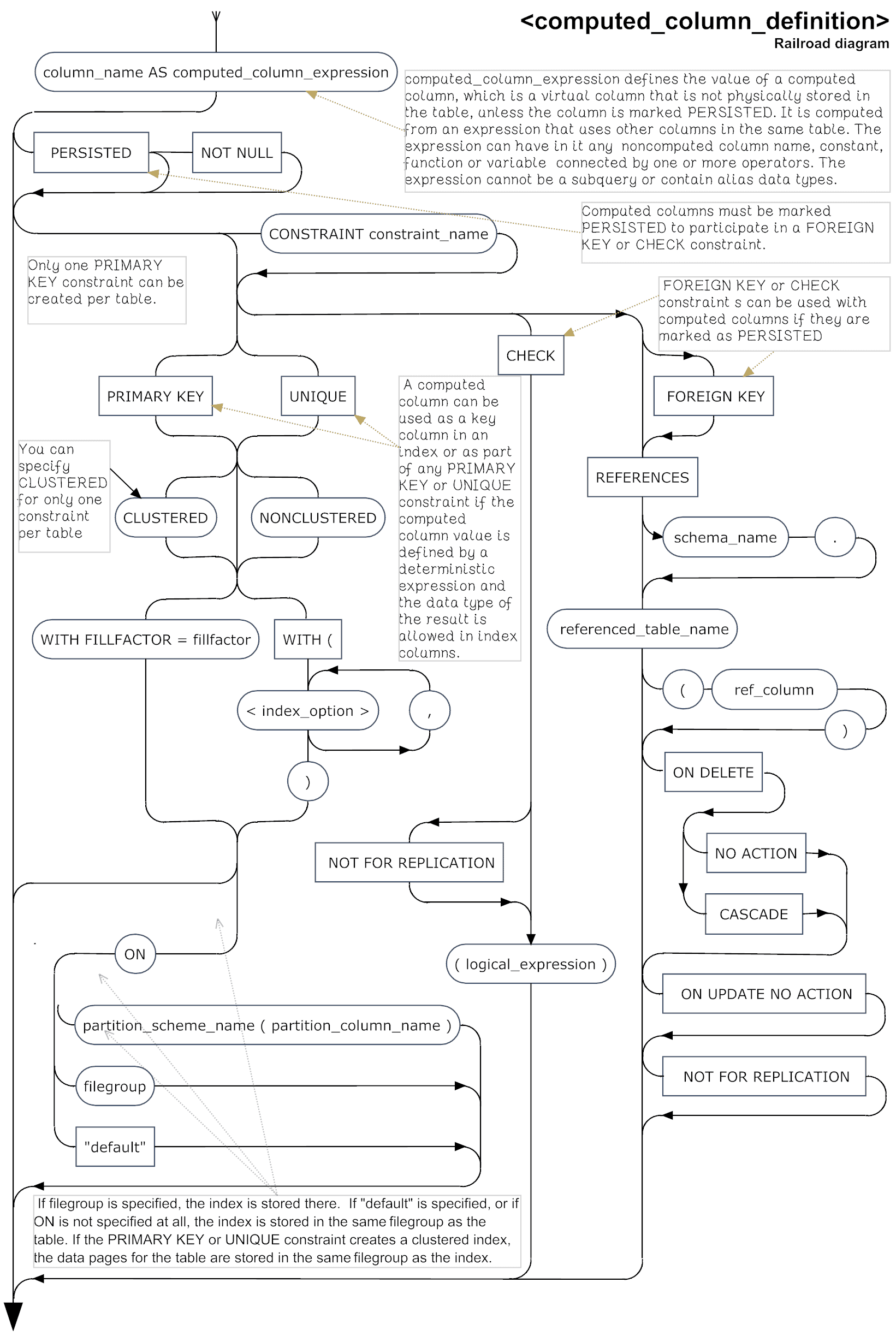
Table Options
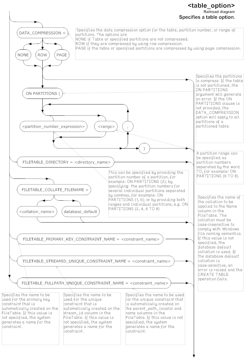
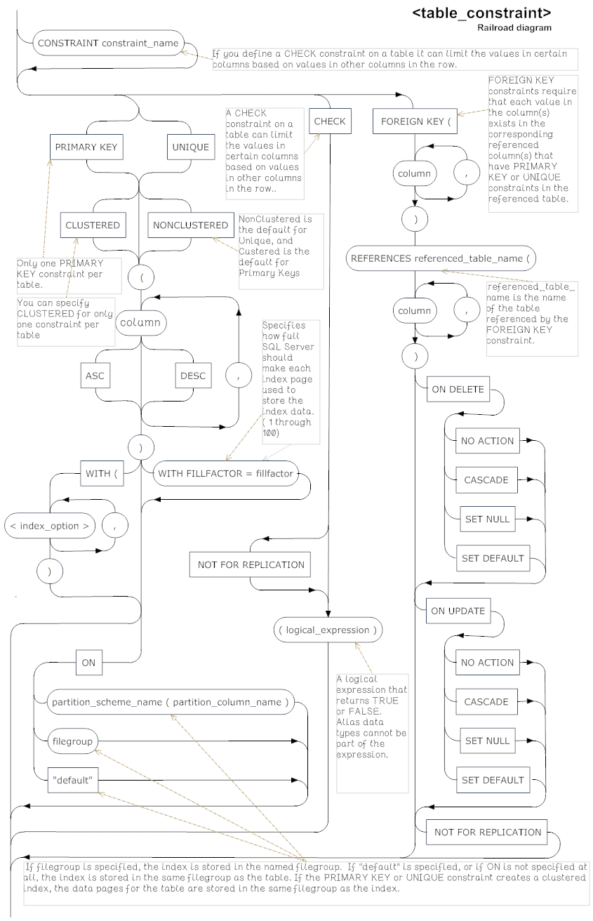
Table Constraint
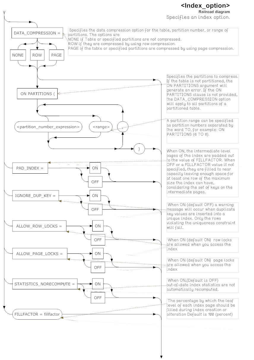
Index Options
Using the Diagrams
I find that I learn a diagram more rapidly than a raw syntax expression. If you are similar, then you soon find that you can dispense with most of the diagrams except for some of the more obscure table creation operations.
When I read through these diagrams, I get the occasional surprise, or reminder of an odd fact I’ve forgotten. For example, the computed_column_definition diagram shows that one can use a computed column, if persisted, to be a reference to a foreign key. One doesn’t even have to specify the column in the foreign table if it is the primary key. IDENTITY fields only need to specify start and increment if they vary from the default.
The MSDN Syntax descriptions
The syntax descriptions provided on MSDN are like Extended Backus-Naur Form (EBNF) but have some conventions from BNF. This is a very simple language.
Angled brackets <> around a symbol, such as the data type example shown below, shows that it is non-terminus and needs a separate definition.
- Optional items are enclosed in square brackets
- Groups of expressions are enclosed in curly braces
- A ‘|’ is a binary operator meaning ‘or’.
This definition of a data type…
|
1 2 3 4 |
<data type> ::= [ type_schema_name . ] type_name [ ( precision [ , scale ] | max | [ { CONTENT | DOCUMENT } ] xml_schema_collection ) ] |
… says that we are defining a data_type symbol (<symbol> ::=). This can start with the schema of the data type (if it is user-defined!), followed by the obligatory type_name. After that, we have a bracket, followed by one of these:
- A specification of precision , and maybe scale (if it is a numeric data type)
- A
MAXqualifier if it is aVARCHAR,NVARCHARorVARBINARYdata types - A specification for an XML schema collection, only to associate an XML type with a schema collection
Finally, we have a closing bracket.
If you see an “n”, it means that the preceding symbol or group can be repeated. For example, [,...n] means that there can be any number of repeats, each separated by a comma.
Summary
The raw BNF of the MSDN documentation is a difficult and error-prone way of trying to understand the syntax of the CREATE TABE statement, or any SQL for that matter. We already know from other database systems that a form of railroad diagrams are a useful aid for understanding how SQL statements work, so why not have them for SQL Server TSQL?
I did these to improve my own understanding and very much hope that you’ll find them as useful as I did. I realize that, for most purposes, a well-designed GUI is the easiest way to do a job on a Windows system but just occasionally, code is just plain easier: and to get up and running, nothing beats a clear syntax diagram.
Acknowledgements
Many thanks to the pioneers of the railroad diagram. Also the MSDN CREATE TABLE page from where the explanatory quotes within the diagrams were taken and adapted.
Load comments